Home /
 From Casting to Cylinder: The Complete CNC Machining Process for Engine Components
Table of Contents
- Step 1: Material Selection & Raw Casting
- Step 2: Initial Setup & Workholding
- Step 3: Rough Milling the Reference Surfaces
- Step 4: Precision Boring of Cylinder Holes
- Step 5: Machining the Crankshaft Tunnel (Bedplate)
- Step 6: Drilling Deep Oil Galleries
- Step 7: Threading and other Features
- Step 8: Surface Finishing & Honing
- Step 9: Final Quality Inspection & Traceability
- Step 10: Packaging & Delivery
- Why KT TOOL for Engine Components Machining?
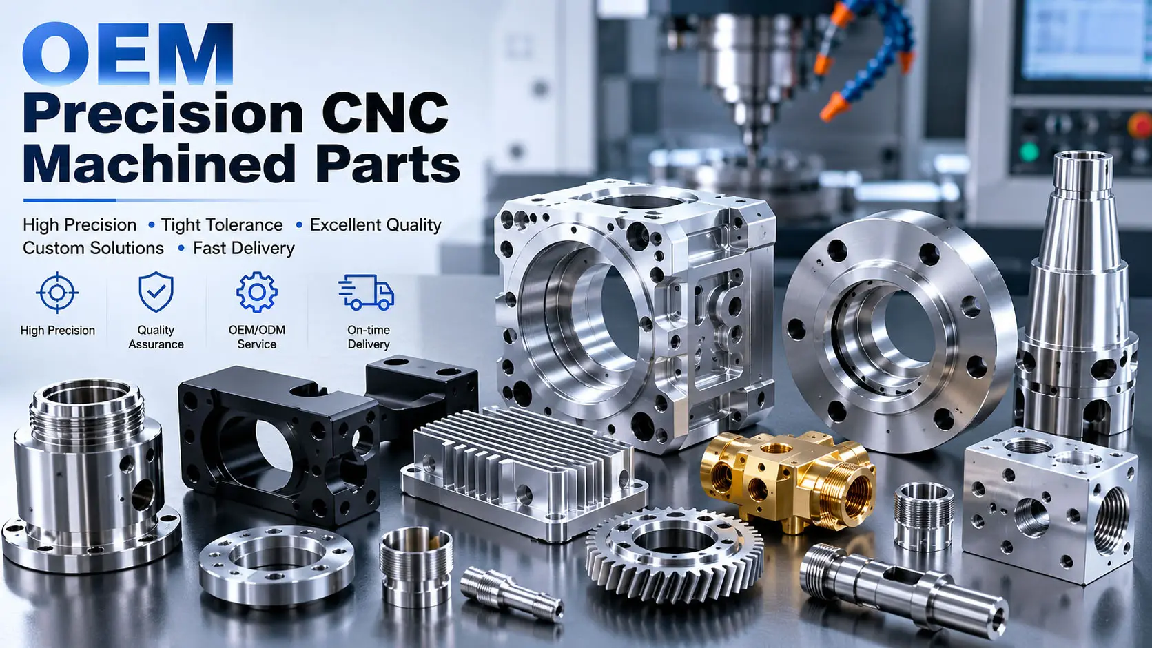
The engine Components form one of the most important part of an internal combustion engine. It is a complex assembly of components, which has many metal passages that transport coolant and oil, as well as several cylinders and passages that can be closed off and sealed to support engine components. Machining gas engine blocks is a highly technical process that, when done correctly, ensures the gas engine block will provide engine power, and operate efficiently and reliably.
For companies like KT TOOL, such a process involves advanced CNC technologies with quality control. KT TOOL applies precise CNC technologies and manufacturing services to the automotive industry. KT TOOL assists with CNC rapid prototyping and low-to-high volume production. The following illustrates all the steps to make a cast that can be used as a cylinder engine block.
Step 1: Material Selection & Raw Casting
The first step of manufacturing is casting. Aluminum and gray iron are standard materials for engine blocks. Although gray iron is much stronger, aluminum is much lighter. For the parts KT TOOL manufactures, aluminum die casting is beneficial because the lighter parts improve fuel efficiency.
•High-Volume Production Capability: For Engine component machining, it is important that casts are made so that the wall thickness has low porosity so that it can withstand the pressures from machining.
•Importance of Grain Structure: A uniform grain structure helps machining and allows for small variations in dimensions after heat-treatment.
Step 2: Initial Setup & Workholding
For the first machining operation, the orientation of the engine block raw cast must be as determined. Because of the asymmetry of the engine block, a custom fixture is necessary.
•Hydraulic & Toggle Clamps: A custom fixture has to be designed with these clamps to secure the block during the high-torque machining operations.
•Locating from Datum Points: For the casting to be positioned in the machine's coordinate system, precision ground pins enable location with respect to the origin.
•Consideration for Thin Walls: Aluminum blocks can be supported with soft jaws, or custom fixtures, to prevent collapse of the thin walls.
Step 3: Rough Milling the Reference Surfaces
Once the first operation has been performed, all features will be referenced concerning the surfaces. These surfaces must be milled to be flat and true.
•CNC Milling with 3-Axis Machines: During the rough milling operation, the casting scale and sprue remnants will be eliminated from the top, bottom and front/rear faces.
•Tolerances to ±0.01mm: Even with roughing, we still need to take care about the flatness of the surfaces. KT TOOL will provide a standard surface finish on reference faces of Ra 0.8–1.6μm.
•Coolant Application: To keep the cast iron dust from dulling the cutting tools, a high pressure coolant will be used to flush the dust away.
Step 4: Precision Boring of Cylinder Holes
This operation is one of the most difficult during the machining of Engine Components. The machining of the holes is required to be round and straight.
•Semi-Finish Boring: In this operation, a roughing boring bar will leave a remainder of 0.3–0.5mm for finishing.
•Tight Tolerance Machining for Critical Parts: KT TOOL has developed the expertise to perform price boring of automotive components to achieve a high level of roundness and straightness of bores and tolerances within microns.
•Indexable Insert Tool: Because of the long, stringy chips generated during this operation, a chip breaker carbide insert was used.
Step 5: Machining the Crankshaft Tunnel (Bedplate)
The bedplate of the block houses the crankshaft bearings. It's critical that top block and bedplate are parallel.
•Line Boring: Torque plates lock the block and bedplate in place, and the main bearing journals are cut.
•Bearing Alignment: The crankshaft will bind and the engine will fail if the main bore alignment is off by 0.01mm.
•CMM for Full Traceability: All four main bores are measured. Each order includes a CMM inspection and material certificates from KT TOOL. This provides assurance that you can be certain the specifications are met with full traceability.
Step 6: Drilling Deep Oil Galleries
Oil galleries transport oil from the pump to the crankshaft and camshafts.
•Gun Drilling: A gun drill is a straight fluted drill which can be 20 times its diameter deep. Gun drills are patented and oiled under high pressure to remove chips.
•Tool Deflection: To gun drill deep and lessen defection of the hard scale of the casting, a short and very rigid starter drill is used.
Step 7: Threading and other Features
Holes on the block are threaded for head bolts, main caps, oil nozzles and other components.
•Form Tapping vs. Cut Tapping: Of the two, form tapping is adopted in aluminum blocks since it does not leave behind a chip as compared with cut tapping which leaves behind excess metal in the form of swarf.
•Thread Connectors and Plugs: The plugs for oil and coolant can be sealed without gaskets, as the threads remain intact.
•Multi-Axis Machining: At KT Tool, surfaces can be machined and angled bolt holes can be placed with the aid of complete 5-axis concurrent machining, allowing for complete setups without error from repositioning.
Step 8: Surface Finishing & Honing
Machining creates microscopic peaks and valleys, and the final machining step prepares the surface for a seal and for the seating of the piston rings.
•Surface Flatness for Head Gaskets: The surfaces of the deck are required to be flat to an Ra of ≤ 1.0μm to provide a perfect seal, and are accomplished by milling with a wiper insert.
•Platform Honing: A cross-hatch pattern is formed in the walls of the cylinder using a rotary stroke of a diamond hone. This pattern retains oil for lubrication of the piston rings.
•Anodizing & Sandblasting Services: KT Tool provides anodizing & sandblasting services at the end of their aluminum block production line.
Step 9: Final Quality Inspection & Traceability
Blocks will not go to assembly until all the key criteria have been confirmed.
•CMM (Coordinate Measuring Machine) Inspection: Automated probes measure the position, depth, and diameters of all the bores and compare them to the 3D CAD models.
•Pressure Testing: Oil and water jackets are pressurized to test for porosity leaks using hot air (or liquid).
•Material Certification: KT Tool provides material certification for every order to ensure the specific alloy meets the required certification of either the SAE or the ASTM.
Step 10: Packaging & Delivery
Ready to Market Services for Machined Parts
•Anti-Rust Coating: Iron blocks receive a spray of the Vapor Corrosion Inhibitor (VCI) and aluminum blocks are cleaned and dried.
•Cleanroom Packaging: To make sure the blocks are not contaminated by dust, a plastic seal is used.
•Integrated Manufacturing from Prototyping to Mass Production: KT TOOL's logistics system provides either 10 prototypes to develop a new vehicle or 10,000 for production.
Why KT TOOL for Engine Components Machining?
Engine Components Machining is a combination of metal cutting science and automotive manufacturing business. KT TOOL covers all of it.
•70+ CNC Centers: Includes DMG MORI, Mazak, and Haas for 3/4/5-axis.
•Tolerances Down to ±0.001mm: For critical features such as bearing bores and cylinder roundness.
•Rapid Prototype to Production Transition: We have affordable DFM.
•ISO 9001:2015 Certified: We offer consistent quality from the first article to the millionth part.
Are we ready to machine your next engine block?
Get Free Quote
FAQs
Q1: Which materials do you usually use to machine engine blocks?
Typically, we use gray cast iron and aluminum as both allow for heat and wear resistance, and especially with aluminum, reduce weight for electric vehicles as well as internal combustion vehicles.
Q2: Why is CMM inspection highly necessary in the machining of engine components?
CMM inspection is necessary to ensure that there are absolutely no defects, as it provides full inspection and traceability by verifying the position, depth, and diameter of all the engine component holes and bores with respect to the 3D CAD File.
Q3: Is it possible to use the same CNC machine to rough and to finish the engine block?
Yes, but tools that are used to rough remove large amounts of material while tools that are used to finish operate on surfaces that have a large amount of close tolerance of approximately ±0.001 mm.
Q4: What are the effects of surface finish on the performance of the block?
A deck surface that is too rough can lead to poor sealing of the head gasket, while the cross-hatch finish of the engine block cylinder can help retain oil which is crucial in lubricating the piston rings.
Q5: Does KT Tool allow for low volume engine design prototypes?
Yes, we see all types of orders from one-day rapid prototyping to mass production