Contact Us
 Home /
Automotive Stamping Die Design: How Tooling Accuracy Affects Final Part Tolerance


Table of Contents
- Why Tooling Accuracy Matters in Automotive Stamping
- How Die Errors Transfer Into the Finished Part
- Die Clearance Is a Functional Variable
- Material Behavior Can Override Tool Precision
- From Die Manufacturing to Trial Stamping
- Why Trial Parts and Measurement Matter More Than Machine Accuracy
- Initial Accuracy Is Not Production Capability
- What Buyers Should Evaluate in an Automotive Stamping Supplier

In Automotive Stamping, a die manufactured to a tight tolerance does not automatically produce a stamped part with the same tolerance. Final dimensional accuracy is created by an entire system: part geometry, sheet material, die architecture, punch-to-die clearance, press behavior, springback, tool wear and measurement control.
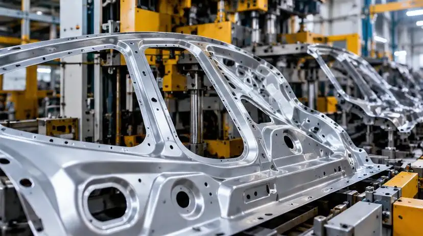
For this reason, tooling accuracy should be treated as the geometric foundation of Automotive Stamping—not as the only source of part accuracy.
Why Tooling Accuracy Matters in Automotive Stamping
Every stamped feature begins with a tooling reference. Punches define holes and cut profiles, forming inserts control bends and drawn surfaces, while pilots and guide systems determine how accurately the strip and upper/lower dies are positioned.
A practical way to understand Automotive Stamping variation is:
Final Part Variation = Tooling Variation + Material Variation + Press Variation + Process Variation + Measurement Variation
This is not a tolerance calculation formula, but it explains why a ±0.01 mm tooling feature does not necessarily create a ±0.01 mm stamped dimension.
Critical tooling elements include:
•Pilots and locating features;
•Guide pillars and bushings;
•Stripper plates;
•Forming inserts and radii;
•Station-to-station positioning in progressive dies.
Their tolerances must be allocated according to the function of the finished part rather than making every tooling dimension unnecessarily tight.
How Die Errors Transfer Into the Finished Part
Tolerance stack-up becomes especially important in progressive Automotive Stamping.
A typical dimensional chain may be:
Pilot Position → Strip Position → Punch Position → Forming Station → Final Datum
Small errors at each stage can accumulate. If a pilot is offset, guide clearance has increased, or a punch insert is incorrectly located, the final hole-to-edge or hole-to-hole position can shift even when each individual component remains close to its nominal dimension.
Cutting and forming features also behave differently.
FeatureMain Accuracy DriversPiercing / blankingPunch size, die clearance, alignment, wearBendingDie radius, material strength, springbackDeep drawingMaterial flow, binder force, lubricationProgressive featuresPilot accuracy, station alignment, feed position
This distinction matters when troubleshooting Automotive Stamping tolerance problems.
Die Clearance Is a Functional Variable
Punch-to-die clearance should not simply be made as small as possible.
The correct clearance depends on:
•Sheet thickness;
•Tensile strength and ductility;
•Required edge condition;
•Material type;
•Expected tool life.
Clearance that is too small can increase cutting force, heat, wear and edge-chipping risk. Excessive clearance can increase rollover, fracture angle, burr formation and dimensional variation.
This is why material and thickness must be defined before finalizing the Automotive Stamping die.
Material Behavior Can Override Tool Precision
Two dies manufactured to the same accuracy may produce different results when the workpiece material changes.
High-strength steel can create higher forming loads and stronger springback. Aluminum requires different friction and material-flow control and may introduce galling concerns. Sheet-thickness and mechanical-property variation can also change the final formed geometry.
Springback is particularly important because a formed sheet elastically recovers after pressure is released. Engineers may need to compensate through:
•Die geometry correction;
•Over-bending;
•Forming-stage adjustment;
•Draw-bead or binder-force changes;
•Controlled material flow.
Therefore, Automotive Stamping tolerance should be evaluated using the actual production material, not only the CAD geometry of the die.
From Die Manufacturing to Trial Stamping
A robust tolerance-control process follows a sequence:
Drawing Review → Material & Thickness → Functional Tolerance → Die Architecture → Tool Manufacturing → Die Assembly → Trial Stamping → Measurement → Compensation → Capability Validation
Precision machining is important during the tooling stage because punches, inserts, pilots and locating components establish the die's reference geometry.
At KT, our CNC machining capability covers standard tolerances of approximately ±0.01 mm, while selected critical features can reach approximately ±0.005 mm, depending on part geometry, material characteristics, setup and process conditions.
For stamping tooling, we work to approximately ±0.05 mm typical tooling tolerance, with high-precision tooling capability reaching around ±0.02 mm. For selected Tool & Die features, critical dimensions can reach approximately ±0.005 mm under suitable manufacturing and inspection conditions.
We treat these values as manufacturing capability references rather than universal tolerance guarantees for every Automotive Stamping project. The achievable tolerance of a finished stamped part still depends on material thickness and strength, part geometry, die architecture, springback, press stability, tooling wear and the inspection strategy used during production.
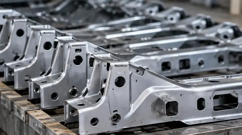
Why Trial Parts and Measurement Matter More Than Machine Accuracy
After die assembly, the real test is the stamped component.
At KT, our progressive stamping capability references finished-part tolerances of approximately ±0.01–0.05 mm, depending on part geometry, feature complexity, material behavior and the overall stamping process.
For automotive progressive-die applications, we typically reference approximately ±0.05 mm for standard features, while selected critical dimensions can reach approximately ±0.01 mm under suitable tooling, material and process conditions.
We treat these values as capability references rather than fixed tolerances for every Automotive Stamping project. Final achievable accuracy should always be evaluated against the actual drawing, material specification, forming sequence and dimensional relationships of the part.
Actual achievable tolerance still depends on the drawing, material, forming sequence and feature relationships.
Trial stamping should therefore verify:
•Dimensional position relative to datums;
•Hole and cut-profile geometry;
•Bend angle and springback;
•Flatness and formed surfaces;
•Burr condition;
•Repeatability across multiple parts.
CMM, gauges or profile measurement can then identify where die compensation is necessary.
Initial Accuracy Is Not Production Capability
A good first-off part does not prove a stable Automotive Stamping process.
During mass production, punch edges wear, guide systems develop clearance and forming surfaces change friction characteristics. These effects can gradually cause dimensional drift.
Production control should therefore include:
Tool Wear Monitoring + Preventive Maintenance + SPC + Cp/Cpk Review + Measurement-System Control
For example, punch wear may increase burr height before a dimension moves outside its specification. That makes burr growth a useful maintenance signal rather than only a cosmetic defect.
KT manufactures progressive, compound and single stamping dies and lists tooling materials such as SKD11, SKD61, D2, SKH-9, RM56 and ASP23, with CNC milling, turning and grinding used in die production. Material and tooling selection should be based on wear mode, load, geometry and required production life.
What Buyers Should Evaluate in an Automotive Stamping Supplier
Automotive sourcing teams should look beyond a supplier's quoted machine accuracy.
Ask:
•Which dimensions are considered functionally critical?
•What tolerance applies to the finished stamped part?
•How are progressive-die stations and pilots aligned?
•How is springback compensated?
•How are punches and inserts inspected?
•What happens when tooling begins to wear?
•How is process capability verified before mass production?
The best Automotive Stamping Strategy integrates part requirement, material behavior, tooling precision, die clearance, press stability, inspection, and maintenance into a manufacturing system.
In-house, KT uses a wide variety of machines for CNC, EDM, milling and grinding to support its stamping tooling and inspection services, which integrates die manufacturing and validation. For automotive stamping projects, KT assesses drawings, materials, critical dimensions and expected production volumes to help design a die architecture and tolerance strategy. The integration of stamping and tooling services provides KT the ability to integrate with customers at a wide variety of points along the manufacturing process.
FAQs
Q1. What Automotive Stamping tooling does KT manufacture?
KT manufactures progressive dies, compound dies, single stamping dies and custom automotive stamping tooling.
Q2. What CNC machining tolerance can KT achieve?
KT references standard CNC machining tolerances of approximately ±0.01 mm, with selected critical features reaching about ±0.005 mm.
Q3. What tolerance does KT reference for stamping tooling?
KT references approximately ±0.05 mm typical tooling tolerance, with high-precision tooling capability around ±0.02 mm.
Q4. What tolerance can KT achieve for critical Tool & Die features?
Selected critical Tool & Die dimensions can reach approximately ±0.005 mm under suitable manufacturing and inspection conditions.
Q5. What finished-part tolerance does KT reference for progressive stamping?
KT references approximately ±0.01–0.05 mm, depending on part geometry, material and stamping-process conditions.
Talk to the Manufacturer, Not a Middleman
Resources & Insights
-
 Industry Insights
Custom Aluminum Automation Parts Machining for Robotic Joint Housings
2026-10-21By KT Engineering -
Industry Insights
Automotive Stamping Die Design: How Tooling Accuracy Affects Final Part Tolerance
2026-10-21By KT Engineering -
 Industry Insights
GD&T for Industrial Equipment Parts: Controlling Position, Flatness and Concentricity
2026-10-21By KT Engineering -
 Industry Insights
Inconel Aerospace Components: Managing Heat, Tool Wear and Machining Stability
2026-10-21By KT Engineering