Contact Us
 Home /
Inconel Aerospace Components: Managing Heat, Tool Wear and Machining Stability


Table of Contents
- Why Inconel Is Used for Aerospace Components
- Cutting Heat Is the First Process-Control Problem
- Tool Wear Directly Affects Dimensional Accuracy
- Machining Stability Requires a System Approach
- Why 5-Axis Machining Helps Complex Aerospace Components
- Controlling Dimensional Drift During Long Machining Cycles
- Inconel vs Titanium vs Aluminum Aerospace Components
- What Buyers Should Verify Before Ordering Aerospace Components

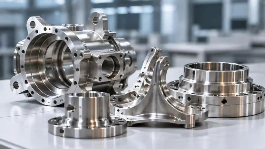
Machining Aerospace Components from Inconel is not simply a matter of selecting a stronger cutting tool. Nickel-based superalloys such as Inconel 718 combine high-temperature strength, low thermal conductivity and strong work-hardening behavior. During CNC machining, these properties create a connected problem: heat accelerates tool wear, tool wear changes cutting forces, and changing forces can gradually affect dimensional accuracy and surface integrity.

For critical Aerospace Components, machining stability therefore depends on controlling the complete process rather than optimizing one cutting parameter in isolation.
Why Inconel Is Used for Aerospace Components
Components subjected to mechanical loads in high temperature corrosive environments are commonly made with Inconel alloys. Mechanical strength of Inconel alloys is well retained at elevated temperatures. As a result, it is a good material choice for applications where the required service temperature exceeds the limit of aluminum or other conventional steels.
However, the properties that benefit the finished component also make Inconel difficult to machine.
| Material Behavior | CNC Machining Effect |
| Low thermal conductivity | Heat concentrates around the cutting zone |
| High hot strength | Cutting forces remain relatively high |
| Work hardening | Previously cut surfaces may become harder |
| High toughness | Chip formation and evacuation become more demanding |
| High tool-interface temperature | Tool wear can accelerate |
The result is that machining Inconel Aerospace Components requires a balance between material removal, tool life and dimensional control.
Cutting Heat Is the First Process-Control Problem
In easier-to-machine materials, part of the cutting heat leaves the cutting zone through the chip and workpiece. In Inconel machining, heat tends to remain concentrated closer to the cutting edge.
The practical chain is:
Higher cutting temperature → Faster edge degradation → Changing tool geometry → Increased cutting forces → Dimensional drift
This is why simply increasing spindle speed to shorten cycle time can be counterproductive. A higher removal rate has little value if premature tool degradation causes the final Aerospace Components to move outside tolerance.
Coolant strategy must therefore consider more than volume. Consistent delivery to the cutting interface, effective chip evacuation and stable thermal conditions are important parts of the machining system.
Tool Wear Directly Affects Dimensional Accuracy
Tool wear in Inconel should not be treated only as a tooling-cost issue.
As flank wear increases, the effective cutting geometry changes. Cutting forces can rise and tool deflection may increase. On long machining cycles, this can create gradual dimensional drift even when the original CNC program remains unchanged.
Work Hardening and Notch Wear
Another challenge is work hardening. If a cutting edge rubs instead of maintaining a controlled cut, the machined layer can become harder. A subsequent pass then encounters a more difficult cutting zone.
This can contribute to:
• Localized notch wear near the depth-of-cut line;
• Unstable cutting forces;
• Edge chipping;
• Increased vibration;
• Inconsistent surface condition.
For Aerospace Components, tool replacement should therefore be based on controlled wear limits and process behavior rather than waiting for complete tool failure.
Machining Stability Requires a System Approach
Stable Inconel machining depends on the relationship between the machine, cutter, holder, fixture, workpiece and toolpath.
Keep the Cutting System Rigid
Excessive tool overhang causes increased deflection and chatter, especially when machining deep pockets and thin walls on Aerospace Components.
Fixtures must also provide enough support to avoid excessive distortion from clamping forces.
Stable Tool Engagement
Cutting conditions vary, causing forces and temperatures to also vary. Shock loading a tool causes sudden, large increases in temperature and may also cause failures in the tool. The toolpath should plan to keep the cutter engaged smoothly and predictably.
Balance the Main Cutting Variables
Cutting speed, feed, axial depth and radial engagement cannot be optimized independently.
For example, an excessively light feed may allow rubbing and work hardening, while aggressive cutting conditions may generate excessive heat and shorten usable tool life. The correct process window depends on material condition, feature geometry, tooling and machine rigidity.
Why 5-Axis Machining Helps Complex Aerospace Components
Complex Aerospace Components may contain compound angles, curved surfaces, deep cavities and features located across several faces.
Five-axis CNC machining can reduce the number of setups required. This matters because every additional setup introduces another opportunity for datum-transfer and re-fixturing error.
For suitable geometry, 5-axis machining can provide:
• Fewer part reorientations;
• Shorter practical tool reach;
• Improved cutter orientation;
• Better access to multi-face features;
• Stronger control of positional relationships between features.
However, 5-axis machining does not automatically guarantee tighter tolerances. Accuracy still depends on tool condition, fixture design, machine calibration, temperature, material stability and inspection strategy.
KT uses 3-axis, 4-axis and 5-axis CNC machining and its CNC department operates more than 70 machines, including machining centers, CNC lathes and mill-turn systems.
KT offers standard machining tolerances of ±0.01 mm, with critical features reaching up to ±0.005 mm. These figures should not be interpreted as universal tolerances for every Inconel component; achievable precision depends on material, geometry, setup and process conditions.
Controlling Dimensional Drift During Long Machining Cycles
A practical process for difficult Aerospace Components may separate material removal from final dimensional control:
Rough machining → Stabilization → Semi-finishing → Tool-condition review → Finishing → Dimensional inspection
The purpose is to avoid removing large amounts of material immediately before critical finishing operations.
In-process measurement can also detect dimensional trends before an expensive Inconel part is completely machined.
KT integrates inspection throughout manufacturing rather than relying only on final inspection. Its published quality-control information covers material control, machining setup, environmental factors and measurement of finished dimensions.
Surface Integrity Goes Beyond Ra
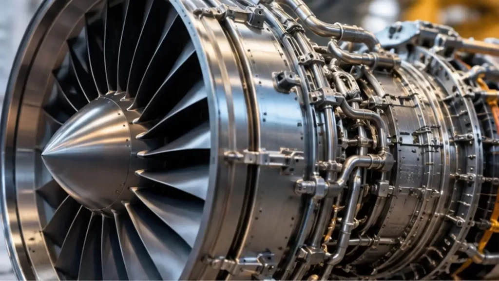
For Aerospace Components, a surface cannot be evaluated only by its roughness number.
Engineering review may also need to consider:
• Tool marks and chatter;
• Burr formation;
• Edge condition;
• Dimensional transitions;
• Heat-related surface effects;
• Fatigue-sensitive surfaces.
A visually smooth part can still be unacceptable if tool wear or unstable machining has affected a critical geometric feature.
Inconel vs Titanium vs Aluminum Aerospace Components
| Factor | Inconel | Titanium | Aluminum |
| High-temperature capability | Very high | Moderate to high | Lower |
| Heat dissipation during machining | Difficult | Difficult | Relatively good |
| Cutting forces | High | High | Lower |
| Tool-wear risk | Very high | High | Lower |
| Practical removal rate | Lower | Moderate-low | Higher |
| Machining difficulty | Very high | High | Lower |
Material selection should follow service requirements first. Machinability should then influence process design, tooling, cost and production planning.
What Buyers Should Verify Before Ordering Aerospace Components
When sourcing Inconel Aerospace Components, buyers should evaluate more than the machine list.
A capable supplier should be able to discuss:
• Experience with difficult-to-machine alloys;
• Datum and fixture strategy;
• Multi-axis machining requirements;
• Tool-life and dimensional-drift control;
• DFM risks such as thin walls and deep cavities;
• CMM or equivalent dimensional verification;
• Material documentation and traceability;
• Inspection requirements for critical features.
This connects the drawing specification directly to a measurable manufacturing and inspection plan.
From Process Stability to Finished Aerospace Components
Producing reliable Inconel Aerospace Components requires heat, tool wear, rigidity, cutter engagement, dimensional control and inspection to be managed as one process. Tight tolerance alone does not define manufacturing capability; the more important question is whether that tolerance can be maintained under the actual material and geometric conditions of the part.
For projects involving complex Inconel or other difficult-to-machine Aerospace Components, KT can review 2D drawings and 3D models, evaluate DFM risks, tolerance requirements and machining strategy, and determine an appropriate multi-axis manufacturing and inspection route before production.
FAQs
Q1. Does KT machine Inconel Aerospace Components?
Yes. KT supports CNC machining of difficult-to-machine materials, including Inconel, for complex precision components.
Q2. What CNC machining processes does KT use for Aerospace Components?
KT operates 3-axis, 4-axis and 5-axis machining centers, CNC lathes and mill-turn systems.
Q3. What machining tolerance can KT achieve?
KT states standard CNC tolerances of ±0.01 mm, with critical features reaching up to ±0.005 mm under suitable conditions.
Q4. Does ±0.005 mm apply to every Aerospace Component?
No. Achievable tolerance depends on material, geometry, feature size, tooling, fixturing, machine condition and inspection requirements.
Q5. How does KT control dimensional drift when machining Inconel?
KT can combine staged machining, tool-condition control, stable fixturing and dimensional inspection to manage accuracy during long machining cycles.
Talk to the Manufacturer, Not a Middleman
Resources & Insights
-
 Industry Insights
Custom Aluminum Automation Parts Machining for Robotic Joint Housings
2026-10-21By KT Engineering -
 Industry Insights
Automotive Stamping Die Design: How Tooling Accuracy Affects Final Part Tolerance
2026-10-21By KT Engineering -
 Industry Insights
GD&T for Industrial Equipment Parts: Controlling Position, Flatness and Concentricity
2026-10-21By KT Engineering -
 Industry Insights
Inconel Aerospace Components: Managing Heat, Tool Wear and Machining Stability
2026-10-21By KT Engineering