Contact Us
 Home /
Metal Component Tolerance Design: How Tight Should CNC Machined Parts Really Be?


Table of Contents
- What Does Tolerance Mean for a Metal Component?
- How Tight Should a CNC-Machined Metal Component Be?
- Six Factors That Determine Practical CNC Tolerance
- When ± Dimensions Are Not Enough
- How Manufacturing Strategy Affects Metal Component Tolerance
- How Should Tight-Tolerance Metal Components Be Inspected?
- A Practical Metal Component Tolerance Decision Framework
- How to Evaluate a Metal Component Manufacturer

A tighter tolerance does not automatically create a better Metal Component. The correct tolerance protects fit, function, sealing, alignment and interchangeability without adding unnecessary machining and inspection burden.
For CNC-machined parts, tolerance should be selected from the functional requirement backward: identify critical features, define datums, consider material and geometry, choose a machining strategy, and confirm how the result will be measured.
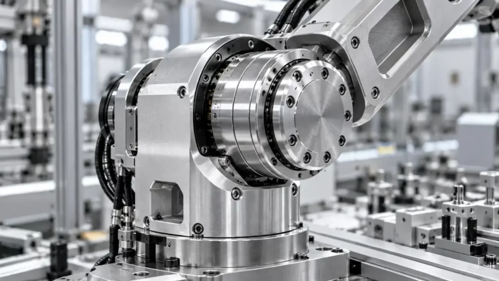
What Does Tolerance Mean for a Metal Component?
Tolerance indicates allowable deviation from the nominal dimension or geometric requirement.
• Dimensional tolerances indicate limits of size on shafts and holes.
• Geometric tolerances are limits of form, orientation and location of features.
A hole may be within diameter tolerance but may still not assemble with a shaft due to incorrect location.
How Tight Should a CNC-Machined Metal Component Be?
There is no universal "best" tolerance for a Metal Component. A cosmetic surface, mounting slot, locating bore and bearing seat perform different functions and should not automatically receive the same tolerance.
| Feature | Typical Design Priority |
| Cosmetic or non-mating surface | Relatively loose |
| General mounting feature | Moderate |
| Locating hole or datum feature | Tighter |
| Bearing seat or precision fit | Tight |
| Sealing or critical interface | Tight and often GD&T-driven |
Apply the tightest tolerance only where function requires it. Over-tolerancing can force extra finishing, tighter tool control, more inspection and higher scrap risk.
Six Factors That Determine Practical CNC Tolerance
1. Material Stability
Aluminum, stainless steel and titanium respond differently to cutting forces, heat and residual stress. Material behavior therefore affects how easily a Metal Component holds its final dimensions.
2. Geometry and Wall Thickness
Thin walls, deep pockets, long slender features and large flat surfaces are more likely to distort during machining or after unclamping.
3. Tool Rigidity and Reach
Excessively long tools increase deflection and decrease rigidity. Deep cavities and small radii may result in the use of smaller or longer tools, also reducing process margin.
4. Workholding and Setup Count
Every re-clamping step can introduce datum-transfer error. Reducing setups can help preserve feature-to-feature accuracy on complex parts.
5. Thermal Stability
Machine, tool and workpiece temperature can shift dimensions when tolerances become very tight. Tighter requirements therefore demand more disciplined process and measurement conditions.
6. Inspection Capability
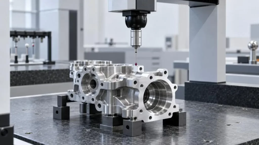
A tolerance is only useful if it can be verified. General dimensions may use calipers or micrometers, while tighter size, position and geometric requirements may need bore gauges or CMM inspection.
When ± Dimensions Are Not Enough
A Metal Component drawing should use GD&T when function depends on relationships between features rather than size alone.
• Position controls feature location relative to datums.
• Flatness controls surface form.
• Perpendicularity controls orientation.
• Profile controls complex contours.
This is often more functional than applying unnecessarily tight ± values to every coordinate dimension.
How Manufacturing Strategy Affects Metal Component Tolerance
Machining sequence matters. A practical route may be:
Rough machining → Stress redistribution → Semi-finishing → Finishing → Inspection
For critical holes, boring or reaming may be more suitable than simple drilling. For complex multi-face parts, 5-axis machining can reduce re-fixturing and datum-transfer error, but 5-axis does not automatically make every part more accurate. Geometry, feature relationships, material, fixturing and inspection strategy still determine the final result.
At KT, our CNC department operates more than 70 machines, including 3-axis, 4-axis and 5-axis machining centers, CNC lathes and mill-turn systems.
For general machining, our standard tolerance capability is typically around ±0.01 mm, while critical features can reach up to ±0.005 mm under suitable manufacturing and inspection conditions.
Our tolerance guidance also references typical CNC machining tolerances around ±0.05 mm, depending on the application. Rather than applying one tolerance value to every Metal Component, we evaluate material stability, part geometry, feature size, setup strategy, machining process and inspection requirements before determining what level of precision can be achieved reliably.
How Should Tight-Tolerance Metal Components Be Inspected?
Measurement method should match the requirement.
| Requirement | Typical Verification Method |
| General external size | Caliper or micrometer |
| Bore diameter | Bore gauge / micrometer |
| Hole position | CMM |
| Flatness or perpendicularity | CMM or suitable metrology |
| Surface roughness | Roughness tester |
For production, buyers should distinguish between making one conforming part and repeating the requirement across a batch. Repeatability depends on stable workholding, tool management and inspection.
A Practical Metal Component Tolerance Decision Framework
Before releasing a drawing:
- Define the functional requirement.
- Identify mating, locating, sealing and load-bearing features.
- Establish functional datums.
- Apply tight tolerances only to critical features.
- Check material stability and geometry.
- Select the machining process and setup strategy.
- Define the inspection method.
- Review cost and repeatability.
The decision chain is:
Function → Critical Feature → Material & Geometry → Tolerance / GD&T → Machining Strategy → Inspection → Cost → Supplier Capability
How to Evaluate a Metal Component Manufacturer
Do not judge a supplier only by its smallest advertised tolerance. Ask whether the requirement is realistic for the feature, material and geometry; how datums are maintained; how it will be measured; and whether the result is repeatable in production.
KT combines drawing review and DFM with multi-axis CNC machining and staged inspection. Its published CNC information also states that CMM inspection is used to verify critical dimensions and geometric relationships.
Match Tolerance to Function Before Manufacturing
The intent of Metal Component tolerance design isn’t to state the least amount of tolerances. The design should incorporate enough dimensional and geometric controls to reliably assemble and function the part and to keep the process manufacturable and measurable.
For Metal Component projects involving tight fits, complex geometries and critical feature relationships, KT can provide a DFM review of the drawings. KT can evaluate how material, machining strategy and tolerancing and inspection affect the overall process before production. Engineers and sourcing teams can use KT's website to assess CNC machining capabilities and use a drawing review to determine a tolerancing strategy.
FAQs
Q1. What tolerances can KT achieve for a Metal Component?
KT's standard machining tolerance is typically around ±0.01 mm, while critical features can reach up to ±0.005 mm under suitable conditions.
Q2. Does KT apply ±0.005 mm tolerance to every Metal Component?
No. Achievable tolerance depends on material, geometry, feature size, setup strategy, machining process and inspection requirements.
Q3. What CNC machining equipment does KT use?
KT operates more than 70 CNC machines, including 3-axis, 4-axis and 5-axis machining centers, CNC lathes and mill-turn systems.
Q4. Can KT review Metal Component tolerances before production?
Yes. KT can review drawings from a DFM perspective to identify unnecessary tight tolerances and potential manufacturing risks.
Q5. Does KT provide 5-axis machining for complex Metal Components?
Yes. KT uses 5-axis machining for complex geometries where reducing setups can help maintain feature-to-feature relationships.
Talk to the Manufacturer, Not a Middleman
Resources & Insights
-
 Industry Insights
Custom Aluminum Automation Parts Machining for Robotic Joint Housings
2026-10-21By KT Engineering -
 Industry Insights
Automotive Stamping Die Design: How Tooling Accuracy Affects Final Part Tolerance
2026-10-21By KT Engineering -
 Industry Insights
GD&T for Industrial Equipment Parts: Controlling Position, Flatness and Concentricity
2026-10-21By KT Engineering -
 Industry Insights
Inconel Aerospace Components: Managing Heat, Tool Wear and Machining Stability
2026-10-21By KT Engineering