Contact Us
 Home /
GD&T for Industrial Equipment Parts: Controlling Position, Flatness and Concentricity


Table of Contents
- Why ± Tolerances Are Not Enough
- Position Controls Where Critical Features Must Be
- Flatness Protects Mounting and Sealing Surfaces
- Concentricity Requires Careful Interpretation
- Machining Strategy Affects GD&T Results
- GD&T Must Be Verified, Not Assumed
- Avoid Over-Tolerancing Industrial Equipment Parts

A machined component can pass every basic ± dimensional check and still fail during assembly. A bolt pattern may be the correct diameter but shifted from its datum. A mounting surface may meet thickness limits but distort under assembly. A bearing bore may be within size tolerance while its axis is misaligned with another bore.
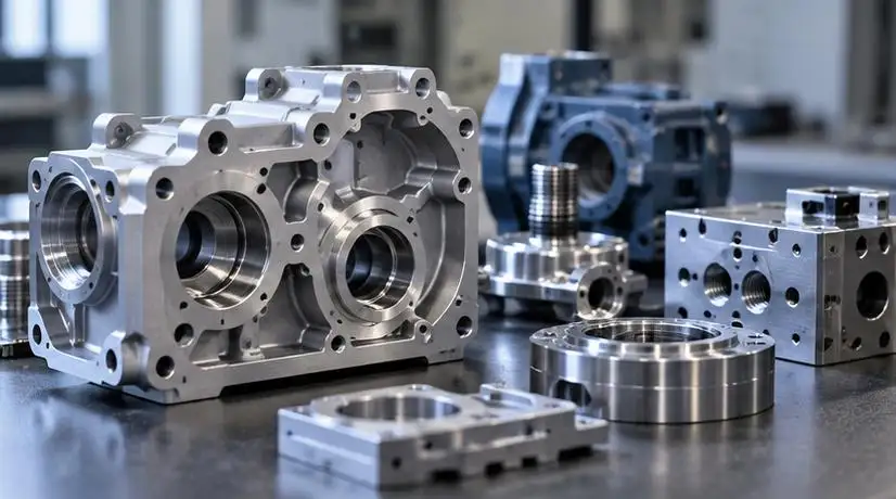
For Industrial Equipment Parts, these problems are why dimensional tolerances alone are often insufficient. Geometric Dimensioning and Tolerancing (GD&T) defines not only feature size, but also form, location, orientation and relationships between critical features.
The practical engineering chain is:
Functional requirement → Datum selection → GD&T control → Machining strategy → Inspection → Supplier verification.
Why ± Tolerances Are Not Enough
Consider a housing with four mounting holes. Each hole may satisfy its diameter tolerance, yet the housing can still fail to assemble if the hole pattern is displaced.
GD&T separates different requirements:
| Functional Requirement | Typical Control | Common Application |
| Locate holes or bores | Position | Bolt patterns, bearing bores |
| Control surface form | Flatness | Mounting and sealing faces |
| Control rotating surfaces | Circular/Total Runout | Shafts, hubs, bearing seats |
| Legacy coaxial requirement | Concentricity | Older drawings |
This distinction matters because tightening every linear dimension does not automatically control the functional relationship between features.
Position Controls Where Critical Features Must Be
Position tolerance is particularly important for Industrial Equipment Parts containing bolt holes, dowel holes, bearing bores and locating features.
A position callout establishes a tolerance zone around a theoretically exact location defined by basic dimensions. The feature must remain inside that zone relative to the specified datum reference frame.
For example, a gearbox housing may use:
•Datum A: primary mounting surface
•Datum B: locating side
•Datum C: secondary locating feature
•Position control: bearing and fastening holes
If machining or inspection establishes the wrong datum, a feature can be accurately manufactured relative to the machine coordinate system but still be functionally misplaced relative to the assembled equipment.
This is why datum strategy should be determined before deciding how tightly a feature should be machined.
Flatness Protects Mounting and Sealing Surfaces
Flatness controls the form of a surface independently of a datum. This makes it different from parallelism or perpendicularity.
Flatness becomes critical on Industrial Equipment Parts such as:
•Valve and pump mating surfaces;
•Gearbox mounting plates;
•Equipment bases;
•Hydraulic manifolds;
•Linear-motion mounting surfaces.
Poor flatness can create uneven contact pressure, local gaps or distortion when fasteners are tightened.
Large or thin components are particularly difficult. During machining, clamping force may temporarily flatten the workpiece. After unclamping, residual stress and material removal can allow the part to move again.
Therefore, controlling flatness may require more than a finishing pass. Process planning can include rough machining, stress stabilization, controlled fixturing, finishing and final inspection.
Concentricity Requires Careful Interpretation
"Concentric" is often used informally to mean that two cylindrical features share the same center or axis. In GD&T, however, legacy concentricity has a much more specific definition involving derived median points.
More importantly, the concentricity symbol was removed from ASME Y14.5-2018. Position, circular runout or total runout can often provide a more direct functional control. Older drawings referencing earlier ASME revisions may still legitimately contain concentricity requirements.
For modern Industrial Equipment Parts, the choice should follow the actual function:
| Requirement | Usually More Appropriate |
| Locate one bore axis relative to another feature | Position |
| Control radial variation during rotation | Circular Runout |
| Control the complete rotating surface | Total Runout |
| Interpret an older specified median-point requirement | Legacy Concentricity |
Engineers should therefore check the drawing's referenced GD&T standard before interpreting the symbol.
Machining Strategy Affects GD&T Results
GD&T capability is not determined by machine accuracy alone.
Critical variables include:
Material stability + Datum strategy + Fixture design + Cutting sequence + Tool condition + Setup count + Temperature + Inspection method
Multiple setups deserve particular attention. If two bearing bores are machined in separate setups, datum transfer between fixtures can introduce additional relationship error.
For complex Industrial Equipment Parts, 4-axis or 5-axis machining can sometimes reduce re-fixturing by allowing several related features to be produced in one controlled setup. That does not mean 5-axis machining is automatically more accurate; the benefit depends on geometry, workholding, machine condition and process planning.
At KT, we operate more than 70 CNC machines, including 3-axis, 4-axis and 5-axis machining centers, CNC lathes and mill-turn systems. Our standard machining tolerance is typically ±0.01 mm, while critical features can reach ±0.005 mm when the part geometry, material and process conditions allow.
However, we do not use one tolerance value as a standard for all Industrial Equipment Parts. We offer roughly machinable tolerances are around ±0.05 mm. Which tolerances are achievable depends, among others, on the material, part geometry, machine and fixture setup, machining strategy, and measuring capabilities and conditions.
For this reason, we use these figures as capability references rather than fixed promises for every component. For Industrial Equipment Parts with critical GD&T requirements, we evaluate the drawing, functional datums, feature relationships and inspection method before confirming the appropriate manufacturing tolerance.
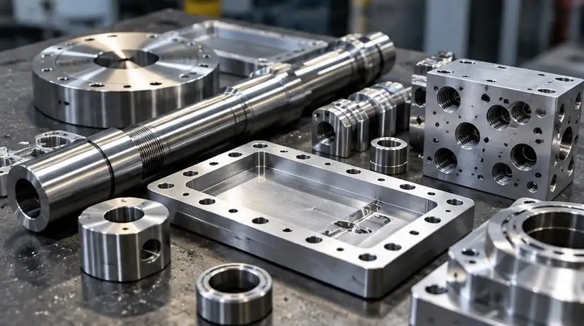
GD&T Must Be Verified, Not Assumed
A drawing requirement is not proof that the manufactured part meets it.
Inspection methods should match the characteristic being controlled:
•Position: CMM or appropriately designed functional gauges
•Flatness: CMM, surface plate or suitable metrology system
•Runout: controlled datum setup with indicator or advanced metrology
•Complex feature relationships: CMM referenced to the drawing datum structure
At KT, we integrate quality inspection throughout the manufacturing process, from incoming material verification to in-process inspection and final validation. For Industrial Equipment Parts with critical dimensional or GD&T requirements, we use CMM inspection as part of our quality-control process to verify feature location, geometric relationships and other specified tolerances before shipment.
Avoid Over-Tolerancing Industrial Equipment Parts
Tighter GD&T is not automatically better.
A 0.01 mm geometric requirement can require more controlled machining, fixturing and measurement than a 0.05 mm requirement. If the tighter value does not protect a functional interface, it may add cost without improving the assembly.
Before releasing Industrial Equipment Parts for production, engineers should ask:
•Which features establish the functional datums?
•Which holes or surfaces actually affect assembly?
•Is position, flatness or runout controlling the correct failure mode?
•Can critical relationships be machined in fewer setups?
•How will each GD&T requirement be inspected?
•Can the supplier provide dimensional or CMM reports?
The most effective GD&T strategy connects every tolerance to a mechanical function.
For parts with complicated Datums, Multi-Face machining or critical Geometric relationships, KT can examine 2D drawings and 3D models to evaluate feasibility of machining tolerances and assessment of inspection requirements prior to production. Multi-axis CNC Machining and Metrology provide a pathway for manufacture, when a combination of critical Geometry and GD&T cannot be resolved.nspection requirements before production. Its multi-axis CNC and metrology capabilities provide a practical manufacturing route when geometry and GD&T requirements must be considered together.
FAQs
Q1. What Industrial Equipment Parts can KT machine?
KT machines housings, shafts, brackets, valve parts, pump components, transmission parts and other precision CNC components.
Q2. What CNC machining processes does KT offer?
KT provides 3-axis, 4-axis and 5-axis CNC milling, CNC turning and mill-turn machining.
Q3. What machining tolerances can KT achieve?
KT offers the standard machining tolerances of around ±0.01 mm, with critical features reaching ±0.005 mm when geometry and process conditions allow.
Q4. Does every Industrial Equipment Part qualify for ±0.005 mm tolerance?
No. Achievable tolerance depends on material, geometry, fixturing, machining strategy, equipment and inspection conditions.
Q5. Can KT machine Industrial Equipment Parts with GD&T requirements?
Yes. KT can manufacture parts with requirements such as position, flatness, runout and other geometric controls based on drawing specifications.
Talk to the Manufacturer, Not a Middleman
Resources & Insights
-
 Industry Insights
Custom Aluminum Automation Parts Machining for Robotic Joint Housings
2026-10-21By KT Engineering -
 Industry Insights
Automotive Stamping Die Design: How Tooling Accuracy Affects Final Part Tolerance
2026-10-21By KT Engineering -
Industry Insights
GD&T for Industrial Equipment Parts: Controlling Position, Flatness and Concentricity
2026-10-21By KT Engineering -
 Industry Insights
Inconel Aerospace Components: Managing Heat, Tool Wear and Machining Stability
2026-10-21By KT Engineering