Contact Us
 Home /
Custom Aluminum Automation Parts Machining for Robotic Joint Housings


Table of Contents
- Aluminum Selection: 6061-T6 vs. 7075-T6
- Lightweight Structures Increase Distortion Risk
- Why 5-Axis CNC Matters for Robotic Housings
- Functional Tolerancing Instead of Tight Tolerancing Everywhere
- KT Machining Precision References
- Datum Strategy Determines Assembly Accuracy
- Inspection Must Verify Geometry, Not Just Size
- From Prototype to Repeatable Production

A robotic joint housing is a structural and geometric reference for bearings, shafts, reducers, motors, locating features, and mounting surfaces. Its machining quality directly affects assembly alignment, rotational accuracy, and load transmission.
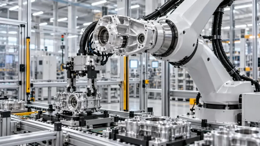
For this reason, Custom Aluminum Automation Parts Machining for robotic joint housings is not only about holding linear dimensions. The manufacturing process must control material stability, bore geometry, datum relationships, thin-wall deformation, multi-face machining, and functional inspection as one connected system.
Aluminum Selection: 6061-T6 vs. 7075-T6
Even though 7075-T6 has a higher ultimate tensile strength than 6061-T6, that doesn't mean that 7075-T6 is always the superior choice.
| Engineering Factor | 6061-T6 | 7075-T6 |
| Strength | Moderate | Higher |
| Machinability | Good | Good |
| Corrosion resistance | Generally better | Requires more consideration |
| Material cost | Lower | Higher |
| Typical application | Frames, brackets, general housings | High-load lightweight robot housings |
For Custom Aluminum Automation Parts Machining, 6061-T6 is often suitable when moderate strength and good corrosion resistance are sufficient. 7075-T6 becomes more relevant when a housing requires higher strength-to-weight performance or extensive material removal for lightweighting.
At KT, we have used 7075-T6 aluminum for robotic main-joint housings combining:
• Complex internal cavities;
• Multi-directional mounting interfaces;
• Bearing seats;
• Thin-wall regions;
• Lightweight rib and pocket structures.
The material decision is therefore linked to both mechanical design and machining stability.
Lightweight Structures Increase Distortion Risk
Robotic joint designers often remove material to reduce moving mass and rotational inertia. Deep pockets, ribs, thin walls, and hollow sections are effective for weight reduction, but they also make machining more sensitive.
The process relationship is straightforward:
High material removal → Residual stress redistribution → Lower local rigidity → Higher deformation risk
Thin sections can also move under:
• Fixture pressure;
• Cutting force;
• Local heat generation;
• Unbalanced material removal;
• Release from the fixture after machining.
How We Control Thin-Wall Machining
For demanding Custom Aluminum Automation Parts Machining projects, our process planning may include:
• Staged roughing, semi-finishing, and finishing;
• Balanced material removal from opposing regions;
• Controlled clamping force;
• Machining allowance on critical interfaces;
• Optimized tool engagement to reduce cutting load;
• Final machining of bearing and locating features after major material removal.
The objective is not simply to hit tolerance while the part is clamped. The housing must remain dimensionally stable after unclamping and inspection.
Why 5-Axis CNC Matters for Robotic Housings
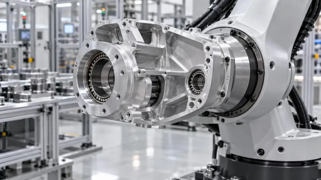
The real value of 5-axis CNC machining is reducing unnecessary datum transfers when critical features are located on multiple orientations.
A conventional multi-setup process may involve:
Machine → Re-clamp → Re-locate → Machine → Re-clamp
Each setup introduces possible errors from:
• Fixture repeatability;
• Datum re-establishment;
• Part seating;
• Probing variation;
• Tolerance stack-up.
At KT, our CNC department operates more than 70 machines, including 3-axis, 4-axis, 5-axis machining centers, CNC lathes, and mill-turn systems.
We select the process based on geometry instead of automatically assigning every part to a 5-axis machine. Simultaneous 5-axis machining can be effective in producing robotic housings with bearing bores and mounting plane alignments.
An important consequence of the reduction in setups is a reduction in datum-transfer error, which can occur regardless of the use of 5-axis machining. There are other factors including fixture design, tool deflection, thermally induced stresses, programming strategy, and inspection that can all contribute to positioning and orientation accuracy.
Functional Tolerancing Instead of Tight Tolerancing Everywhere
A common mistake in Custom Aluminum Automation Parts Machining is specifying extremely tight tolerances on every surface.
That approach increases cycle time and inspection cost without necessarily improving robotic performance.
| Feature | Critical Requirement | Functional Risk |
| Bearing bore | Size, roundness, position | Poor fit or shaft misalignment |
| Paired bearing bores | Coaxial relationship | Rotational error |
| Motor mounting face | Flatness, perpendicularity | Motor/reducer misalignment |
| Dowel or locating holes | Position | Poor assembly repeatability |
| Exterior pocket | General profile | Usually low functional sensitivity |
A bore can meet its diameter tolerance and still fail functionally because of poor roundness or incorrect position relative to the datum system.
KT Machining Precision References
At KT, our CNC capability references approximately ±0.01 mm standard machining tolerance, with selected critical features reaching ±0.005 mm when material, geometry, process conditions, and inspection methods allow.
Our general tolerance guidance also distinguishes between approximately:
• ±0.05 mm for typical CNC machining;
• ±0.005 mm for selected high-precision requirements.
These values are capability references, not universal tolerances for every component.
For one of our 7075 robotic joint housing projects, the specified requirements included:
• Dimensional tolerance: ±0.025 mm;
• Selected critical bore tolerance: ±0.015 mm;
• Bearing-bore roundness: ≤0.008 mm.
This project illustrates why functional features should receive tighter control than non-critical geometry.
Datum Strategy Determines Assembly Accuracy
A robotic housing should be treated as a geometric system rather than a collection of independent dimensions.
A typical relationship may follow:
Primary mounting face → Bearing axis → Locating feature → Motor/reducer interface
If machining, fixture, and inspection references do not follow the same functional logic, individual dimensions may pass inspection while the assembled mechanism still shows alignment error.
At KT, we review datum structure during DFM and process planning to determine:
Which surfaces establish the primary machining reference;
• Which features should remain in the same setup;
• Where re-clamping can introduce risk;
• Which geometric relationships require CMM verification.
This is especially important in Custom Aluminum Automation Parts Machining where several precision interfaces exist on different faces.
Inspection Must Verify Geometry, Not Just Size
Simple dimensions can be checked with calipers, micrometers, or bore gauges. Complex robot housings often require more comprehensive measurement.
Typical verification methods include:
• CMM: position, perpendicularity, flatness, multi-datum relationships;
• Bore measurement: Bearing-seat diameter and fit;
• Roughness testing: Bearing or sealing interfaces;
• 3D scanning: Complex freeform profiles;
Material verification: Alloy and traceability records.
At KT, we combine material verification, in-process inspection, and final validation. For our robotic housing projects, CMM inspection and laser scanning can be used to verify critical geometry relative to defined engineering datums.
From Prototype to Repeatable Production
A successful prototype should validate more than whether one part can be manufactured. It should confirm that the process can be repeated.
For a Custom Aluminum Automation Parts Machining supplier, buyers should evaluate:
• DFM and GD&T understanding;
• Thin-wall deformation control;
• Multi-axis machining capability;
• Fixture repeatability;
• CMM inspection;
• Material traceability;
• Control of critical features across production batches.
We help with development from prototyping to low volume to high volume production at KT. If your design includes 6061 or 7075 aluminum thin walled structures with precision bearing seats and/or multi-face geometry, you can submit your CAD models and/or engineering drawings to KT for a review of your material selection, tolerance, and feasibility of machining and inspection requirements prior to production.
FAQs
Q1. What aluminum alloys does KT machine for automation parts?
KT machines aluminum alloys including 6061 and 7075, depending on strength, weight, corrosion resistance, geometry, and application requirements.
Q2. Can KT machine robotic joint housings?
Yes. KT has experience machining complex robotic joint housings with bearing seats, mounting interfaces, internal cavities, and lightweight structures.
Q3. Does KT provide 5-axis CNC machining for automation parts?
Yes. KT operates 3-axis, 4-axis, and 5-axis CNC machining centers for complex Custom Aluminum Automation Parts Machining projects.
Q4. What machining tolerances can KT achieve?
KT references standard CNC machining tolerances of about ±0.01 mm, with selected critical features reaching ±0.005 mm under suitable process conditions.
Q5. Does every KT-machined part achieve ±0.005 mm tolerance?
No. Achievable tolerance depends on material, geometry, wall thickness, fixture design, machining strategy, and inspection requirements.
Talk to the Manufacturer, Not a Middleman
Resources & Insights
-
 Industry Insights
Custom Aluminum Automation Parts Machining for Robotic Joint Housings
2026-10-21By KT Engineering -
 Industry Insights
Automotive Stamping Die Design: How Tooling Accuracy Affects Final Part Tolerance
2026-10-21By KT Engineering -
 Industry Insights
GD&T for Industrial Equipment Parts: Controlling Position, Flatness and Concentricity
2026-10-21By KT Engineering -
 Industry Insights
Inconel Aerospace Components: Managing Heat, Tool Wear and Machining Stability
2026-10-21By KT Engineering