Contact Us
 Home /
CNC Machining Service and Digital Twins: Reducing Collision and Setup Risk


Table of Contents
- Digital Twin vs Toolpath Simulation in CNC Machining
- Where Collision Risk Actually Comes From
- Why 5-Axis CNC Machining Needs Machine-Level Simulation
- How Virtual Machining Fits into a CNC Machining Service Workflow
- What Virtual Machining Cannot Predict Completely
- KT CNC Machining Accuracy and Process Control
- How to Evaluate a CNC Machining Service for Complex Parts

In complex CNC machining, a valid CAM toolpath is not enough to guarantee a safe machining cycle. The cutter may clear the workpiece while the holder approaches a clamp, a rotary table may enter the spindle envelope, or a post-processed move may exceed a machine-axis limit.
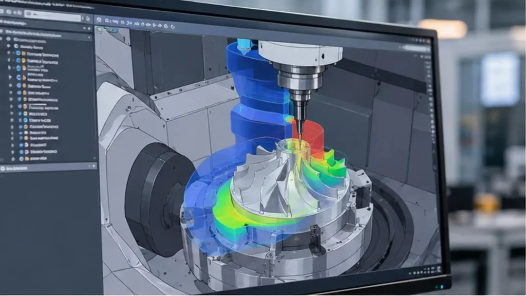
For a CNC Machining Service handling multi-axis and tight-tolerance parts, these risks should be identified before the spindle starts. Digital-twin concepts and machine-level simulation provide a virtual environment for checking machine motion, tooling, workholding and setup logic before physical machining.
Digital Twin vs Toolpath Simulation in CNC Machining
A digital twin is more than a 3D model of the CNC machine. In machining applications, the useful virtual model should represent the elements that determine whether the NC program can actually run:
• Machine kinematics and axis configuration
• X/Y/Z travel and rotary-axis limits
• Tool length, diameter and gauge length
• Tool-holder geometry
• Fixture, clamps and workholding position
• Raw-stock geometry
• Work coordinate system
• Post-processed machine motion
This distinction matters because CAM verification and machine verification solve different problems.
| Verification Level | Main Question | Typical Risks Detected |
| Toolpath simulation | Does the cutter follow the intended geometry? | Gouging, remaining stock, cutter interference |
| Machine simulation | Can the real machine execute the path? | Axis limits, rotary motion, spindle/fixture collision |
| Physical setup verification | Is the real setup consistent with the virtual setup? | Wrong offsets, incorrect tool data, fixture position |
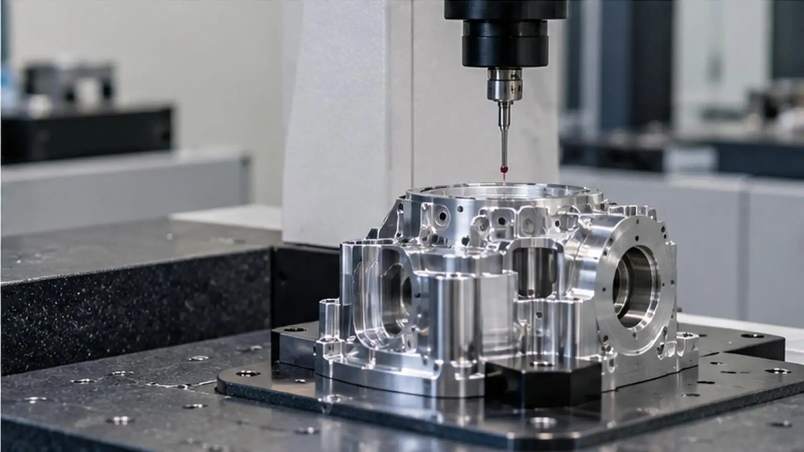
| CMM inspection | Does the finished part meet the drawing? | Size, position, form and datum-related deviation |
A collision-free toolpath therefore does not automatically mean a collision-free CNC Machining Service process.
Where Collision Risk Actually Comes From
Tool and Holder Clearance
Deep pockets and steep walls often require extended tools. However, tool reach is a trade-off.
A short tool may create:
• Holder-to-workpiece interference
• Insufficient access to deep features
Excessive overhang may introduce:
• Higher tool deflection
• Lower dynamic stiffness
• Chatter
• Dimensional variation
• Poorer surface finish
Virtual verification should therefore check the complete tool + holder + spindle envelope, not only the cutting edge.
Fixture and Clamp Interference
Workholding is another major source of collision risk. A fixture that is safe for one operation may enter the tool envelope after the rotary axes reposition the part.
For complex components, we evaluate:
• Clamp height
• Fixture accessibility
• Tool approach angle
• Required clearance during indexing
• Whether machining sequence exposes or blocks later features
This is particularly important when one setup is intended to replace several conventional operations.
Why 5-Axis CNC Machining Needs Machine-Level Simulation
A simultaneous 5-axis system combines three linear axes with two rotary axes. The programmed tool-tip position may remain correct while the machine can reach that same point through different rotary-axis configurations.
That introduces additional variables:
Tool Orientation → Rotary-Axis Position → Spindle Clearance → Fixture Clearance → Machine Travel
Near rotary-axis limits, seemingly small orientation changes may create large machine movements. A post-processor must therefore translate CAM data into motion that matches the kinematic structure and controller of the actual machine.
For our complex 5-axis work at KT, we develop collision-free toolpaths, optimize tool orientation and simulate complex geometries offline before machining. Our published 5-axis process is designed around single-setup machining where appropriate, reducing re-fixturing and the tolerance stack-up associated with repeatedly relocating the same component.
How Virtual Machining Fits into a CNC Machining Service Workflow
At KT, simulation is most useful when it is treated as one stage of process engineering rather than as an isolated software check.
1. Review of DFM and Datum
Before creating toolpaths, we need to review the following:
• Critical dimensions and GD&T
• Functional datums
• Deep cavities and inaccessible features
• Thin walls, and low-rigidity areas
• Clamping areas
• Areas that need to remain in the same setup
This information will help us develop an efficient machining sequence, prior to generating toolpaths.
2. Tooling and Workholding Definition
The virtual environment should match the physical setup as closely as practical. Incorrect holder length or fixture geometry can make a simulation misleading.
3. CAM Programming and Post-Processing
The CAM system creates the cutting strategy, but the post-processor converts that strategy into machine-specific NC code. For a complex CNC Machining Service, verification should consider the post-processed machine movement—not only the original CAM cutter path.
4. Offline Collision Verification
We perform offline simulation to evaluate tool orientation and collision risk for more complex 5-axis geometries.
Some checks include:
• Holder-to-Part clearance
• Fixture Interference
• Movement of Rotary Axis
• Movement of Machine Axis
• Approach and Retract moves
• Tool Change/Repositioning Clearance
5. Physical Setup and First-Article Inspection
Virtual verification does not preclude shop-floor controls. Tool offsets, Work Coordinates and Fixture positions must still be in alignment with approved set-up.
KT integrates inspection throughout production and uses CMM inspection for complex first articles, connecting programming verification with physical dimensional validation.
What Virtual Machining Cannot Predict Completely
Digital simulation reduces geometric and machine-motion risk, but it does not fully model every physical source of machining error.
Important variables still include:
• Residual stress released during material removal
• Cutting-force-induced deflection
• Thin-wall distortion
• Tool wear
• Chatter and spindle dynamics
• Thermal growth
• Fixture deformation
• Material-to-material variation
For example, a simulation can confirm that a cutter safely reaches a 2 mm wall, but it cannot by itself prove that the wall will remain within tolerance after roughing, unclamping and thermal stabilization.
For this reason, a reliable CNC Machining Service needs a connected control chain:
DFM → Setup Strategy → CAM → Machine Simulation → Controlled Machining → In-Process Inspection → Final Verification
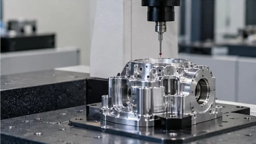
KT CNC Machining Accuracy and Process Control
Our CNC department operates more than 70 machines, including 3-axis, 4-axis and 5-axis machining centers, CNC lathes and mill-turn systems. KT's company profile publishes ±0.01 mm standard machining tolerance, with selected critical features reaching ±0.005 mm.
These values are capability references—not automatic tolerances for every part.
Actual achievable accuracy depends on:
| Factor | Effect on Precision |
| Material stability | Residual stress can move features after cutting |
| Feature geometry | Deep pockets and thin walls reduce rigidity |
| Tool reach | Longer overhang increases deflection |
| Datum strategy | Poor datum transfer increases positional error |
| Number of setups | Re-clamping can create accumulated error |
| Inspection method | Critical tolerances require suitable measurement capability |
This is why we evaluate tolerance requirements by feature rather than applying the tightest tolerance indiscriminately across an entire drawing.
How to Evaluate a CNC Machining Service for Complex Parts
When selecting a supplier, buyers should ask more than how many CNC machines are available.
Useful questions include:
• Are complex multi-axis programs simulated offline?
• Does verification include holders and fixtures?
• Are rotary-axis limits and machine travel checked?
• Is the post-processed program validated?
• How are functional datums maintained between operations?
• Which features require CMM inspection?
• Can dimensional reports be supplied?
• Are tolerance requirements reviewed during DFM?
These questions reveal whether the CNC Machining Service controls the complete process or only generates toolpaths and runs machines.
From Virtual Verification to Machined Parts
Virtual machining is most valuable when it prevents a digital programming problem from becoming a physical machining problem. But simulation alone cannot guarantee dimensional conformity; it must be connected to process planning, stable workholding, controlled cutting and inspection.
At KT, we combine DFM review, offline simulation for complex 5-axis geometry, multi-axis machining and dimensional inspection within the same manufacturing workflow. If you are evaluating a CNC Machining Service for a complex, multi-face or tight-tolerance component, you can send your 2D drawing or 3D model to KT CNC Machining for manufacturability and machining-process review.
FAQs
Q1. What CNC Machining Service does KT provide?
KT provides 3-axis, 4-axis and 5-axis CNC machining, CNC turning and mill-turn machining for precision metal and plastic components.
Q2. Does KT use simulation before 5-axis machining?
Yes. KT uses offline simulation for complex 5-axis geometries to review tool orientation and reduce collision risk before machining.
Q3. What machining tolerance can KT achieve?
KT publishes a standard machining tolerance of approximately ±0.01 mm, with selected critical features reaching ±0.005 mm, depending on part conditions.
Q4. Are ±0.005 mm tolerances available for every CNC part?
No. Achievable tolerance depends on material, geometry, wall thickness, tool access, fixturing, datum strategy and inspection conditions.
Q5. How does KT reduce collision risk in complex CNC machining?
KT combines CAM programming, tool-orientation planning and offline simulation to check complex multi-axis machining before production.
Talk to the Manufacturer, Not a Middleman
Resources & Insights
-
 Industry Insights
Sheet Metal Fabrication Manufacturer: Prototype-to-Production Experience
2026-10-23By KT Engineering -
 Industry Insights
Precision 5 Axis Machining for Medical Components and Surface Finish
2026-10-23By KT Engineering -
 Industry Insights
CNC Machining Service and Digital Twins: Reducing Collision and Setup Risk
2026-10-23By KT Engineering -
 Industry Insights
Custom Aluminum Automation Parts Machining for Robotic Joint Housings
2026-10-21By KT Engineering