Contact Us
 Home /
Precision 5 Axis Machining for Medical Components and Surface Finish


Table of Contents
- Why Medical Parts Require More Than Basic 5-Axis Capability
- Machine Kinematics Directly Influence Part Accuracy
- Tool Orientation Controls Surface Finish
- Thin Walls Require Controlled Material Removal
- Material Behavior Changes the Machining Strategy
- Burr Control Is Part of Precision Machining
- Inspection Must Confirm Geometric Relationships
- KT Precision 5 Axis Machining Capability

Medical components often combine free-form surfaces, thin walls, angled holes, deep cavities, intersecting features, and tightly related datums within one part. The real manufacturing difficulty is not producing each feature separately, but maintaining their geometric relationship while controlling deformation, burrs, tool marks, and surface finish.
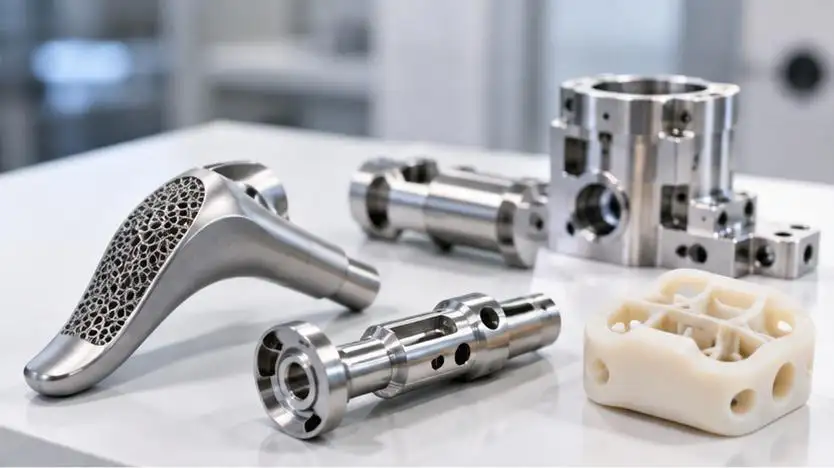
At KT, we use Precision 5 Axis Machining when part geometry, tolerance relationships, and tool accessibility justify simultaneous multi-axis control. The objective is not simply to reduce setups. It is to control the complete relationship between machine kinematics, cutting conditions, part rigidity, and inspection results.
Why Medical Parts Require More Than Basic 5-Axis Capability
A five-axis machine does not automatically produce a high-precision medical component. Accuracy depends on the entire process chain:
• Machine rotary-axis calibration;
• Tool center point compensation;
• Fixture rigidity and datum definition;
• Tool runout and overhang;
• Thermal stability;
• Cutting-force direction;
• Toolpath continuity;
• In-process and final inspection.
For complex medical components, each additional re-clamping operation introduces another potential datum-transfer error.
Machine Coordinate → Fixture Datum → Part Datum → Critical Feature
With Precision 5 Axis Machining, we can often machine several faces and compound-angle features in one setup, reducing the number of coordinate-system transfers.
| Process | Tool Access | Datum Transfers | Typical Application |
| 3-Axis | Fixed direction | Higher | Simple prismatic parts |
| 3+2 Machining | Indexed angles | Moderate | Multi-face features, angled holes |
| Simultaneous 5-Axis | Continuous tool-vector control | Lower | Free-form surfaces, complex medical geometry |
Machine Kinematics Directly Influence Part Accuracy
In simultaneous Precision 5 Axis Machining, linear axes and rotary axes move together. Small rotary-axis errors can therefore create measurable positional deviations at the tool tip, particularly when machining large offsets from the rotary center.
We consider several factors during process planning:
Tool Center Point Control
The programmed tool tip must remain on the intended path while the rotary axes position the tool orientation. Compensating for TCP/RTCP allows us to maintain geometry during simultaneous motion.
Tool Overhang and Deflection
Longer tools provide access to deep cavities but reduce rigidity.
Longer Overhang → Greater Deflection → Higher Chatter Risk → Larger Profile Error
Where possible, five-axis positioning allows us to approach the feature at a better angle and use a shorter tool. This can be more valuable than simply increasing spindle speed or reducing feed.
Rotary-Axis Motion
Rapid changes in A-, B-, or C-axis direction can affect surface continuity. For precision surfaces, we evaluate not only the CAM toolpath but also how that path is physically executed by the machine.
Tool Orientation Controls Surface Finish
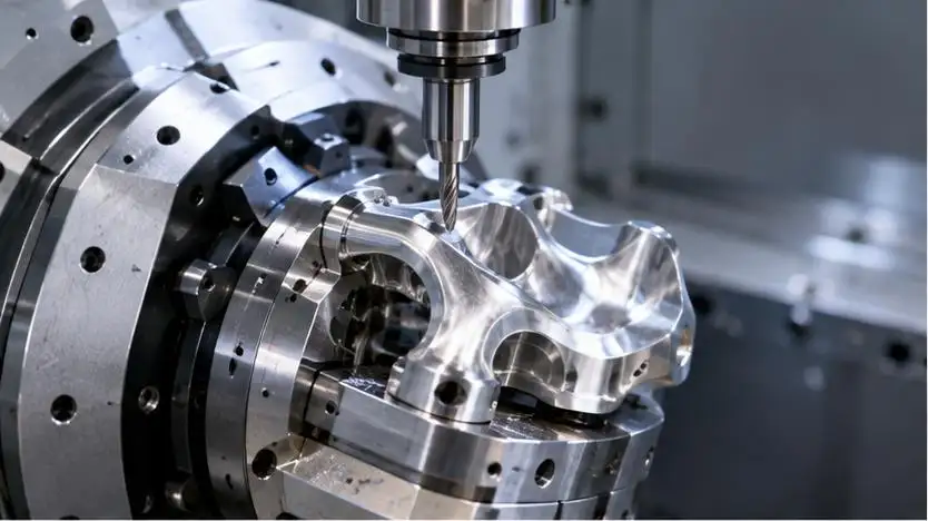
Surface quality in Precision 5 Axis Machining depends strongly on tool orientation.
With a ball-nose cutter, the center of the tool has almost zero effective cutting speed. If the cutter works directly at the tip, rubbing and unstable cutting can occur.
A controlled tilt angle shifts the contact point away from the tool center:
Tool Tilt → Effective Cutting Diameter → Cutting Speed → Cutting Force → Surface Texture
We optimize several parameters together:
• Tool tilt and lead angle;
• Step-over;
• Cutter diameter;
• Feed per tooth;
• Toolpath direction;
• Engagement angle;
• Tool condition.
A smaller step-over normally reduces scallop height, but it also increases machining time. For medical components, the correct value should follow the drawing-defined surface requirement rather than an arbitrary “finest possible” setting.
Thin Walls Require Controlled Material Removal
Thin medical components can distort during machining even when the machine itself is highly accurate.
Typical causes include:
• Residual stress in raw material;
• Excessive clamping force;
• Asymmetric material removal;
• Cutting heat;
• Insufficient wall support.
Our approach may include staged roughing and finishing, balanced stock removal, reduced finishing engagement, and fixture support near low-stiffness regions.
For thin sections, Precision 5 Axis Machining must therefore control both tool position and the mechanical response of the workpiece.
Material Behavior Changes the Machining Strategy
Medical-grade materials cannot be machined with one universal parameter set.
| Material | Main Challenge | Process Priority |
| Titanium | Low thermal conductivity | Heat control and tool-life management |
| 316L Stainless Steel | Work hardening | Stable engagement and sharp cutting edges |
| PEEK | Lower stiffness and thermal sensitivity | Clamping and temperature control |
Titanium
Flank wear and edge breakdown can occur with too much engagement, and this can be worsened by an unstable cutting load. Maintaining the proper amount of engagement requires adequate coolant delivery and high radial engagement of the tool.
316L Stainless Steel
316L can work-harden when the tool rubs instead of cutting cleanly. Conservative but unstable cutting may actually create more difficulty than a properly maintained cutting load.
PEEK
PEEK requires different thinking. Excessive clamping pressure or machining heat can affect dimensional stability, especially around thin walls and small features.
Burr Control Is Part of Precision Machining
A medical component may meet dimensional tolerance but still fail functional requirements because of uncontrolled burrs.
Problem areas include:
• Intersecting holes;
• Cross-drilled passages;
• Narrow slots;
• Internal transitions;
• Thin edges.
We address burr formation through cutter selection, cutting direction, entry/exit strategy, tool condition, and controlled post-machining deburring.
Edge-break requirements should be treated as dimensional features, not cosmetic finishing notes.
Inspection Must Confirm Geometric Relationships
Complex medical components cannot be validated using only basic dimensional tools.
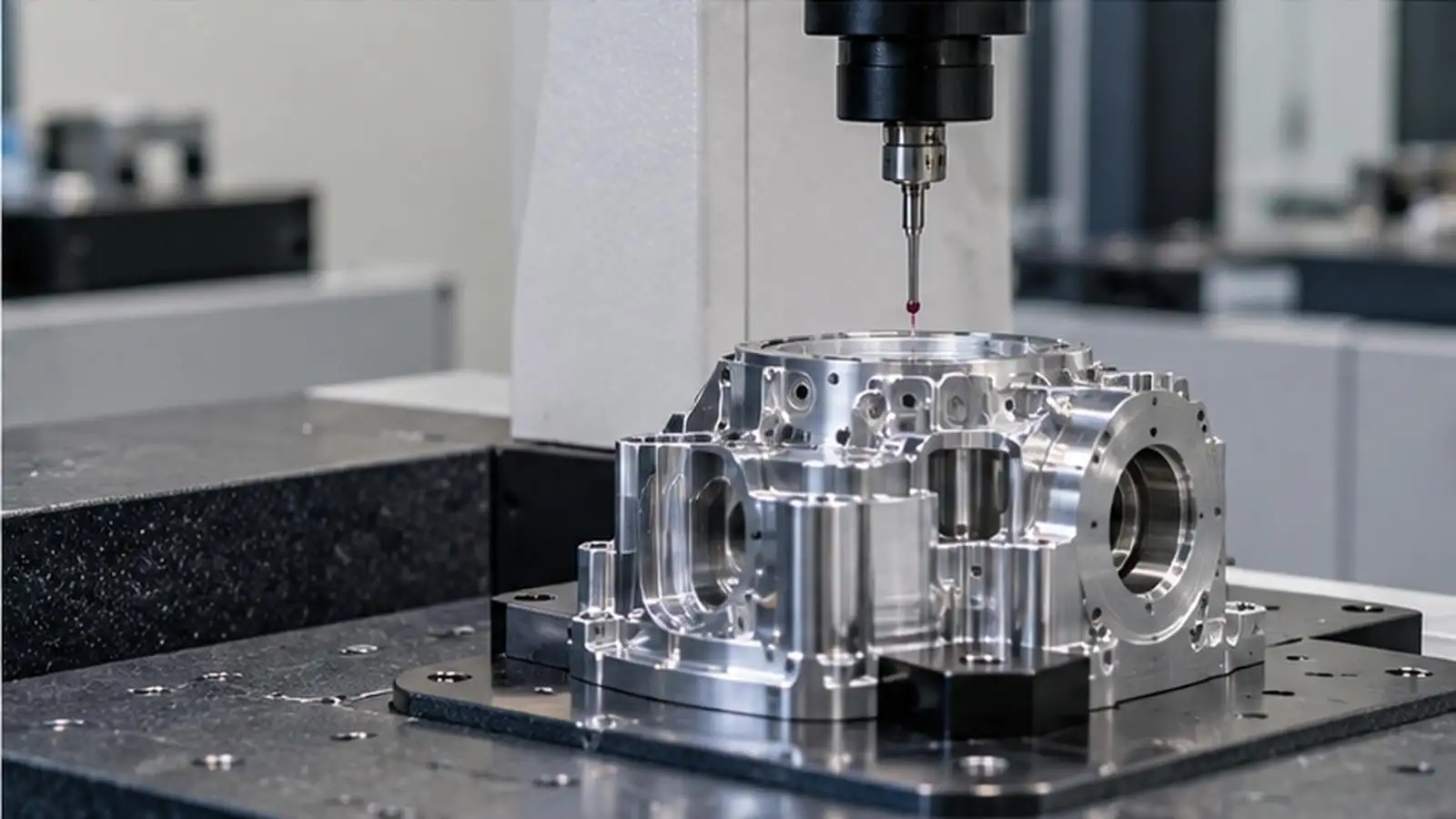
At KT, inspection is integrated into the manufacturing process. Depending on the drawing requirements, CMM inspection can be used to verify:
• True position;
• Surface profile;
• Concentricity;
• Perpendicularity;
• Flatness;
• Datum relationships;
• Multi-surface geometry.
Surface finish must be evaluated separately because dimensional accuracy and roughness describe different conditions.
A part can measure correctly and still contain unacceptable scallop marks, chatter, scratches, or burrs.
KT Precision 5 Axis Machining Capability
Our CNC department operates more than 70 machines, including 3-axis, 4-axis, and 5-axis machining centers, CNC lathes, and mill-turn systems.
Our machining capability:
• Standard machining tolerance: Approximately ±0.01 mm;
• Selected critical features: Up to ±0.005 mm;
• Multi-axis machining for complex surfaces and multi-face parts;
• CMM-supported dimensional verification.
These figures are capability references rather than universal guarantees. Actual achievable tolerance depends on material, feature size, wall thickness, geometry, fixture strategy, tool access, and inspection conditions.
For this reason, we review critical characteristics before production instead of applying the tightest tolerance to every feature.
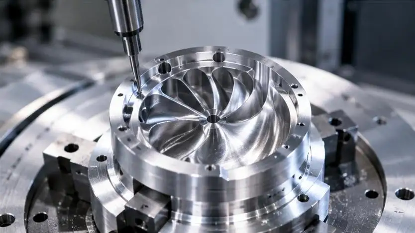
Selecting a Precision 5 Axis Machining Process
The correct manufacturing decision should follow a technical chain:
Part Geometry → Datum Strategy → Material → Tool Access → Cutting Strategy → Surface Requirement → Inspection → Manufacturing Risk
Not every complex part requires simultaneous five-axis motion, and tighter tolerance is not automatically better.
For components containing features such as compound angles, free-form surfaces, difficult tool access, and tight feature relationships, it is important to perform early DFM to determine whether Precision 5 Axis Machining, or 3+2 machining is appropriate.
Prior to production, KT can analyze your drawing/model to evaluate geometry and tolerancing as well as consider the behavior of the material, surface requirements and the method of inspection. Visit https://www.ktcncmachining.com/ for parts requiring an advanced level of precision, to discuss how KT can best manufacture your components.
FAQs
Q1. Does KT provide Precision 5 Axis Machining?
Yes. KT provides 5-axis CNC machining for complex surfaces, multi-angle features, and precision components requiring controlled tool access.
Q2. What tolerance can KT achieve in CNC machining?
KT offers standard machining tolerances of approximately ±0.01 mm, with selected critical features reaching up to ±0.005 mm, depending on the part.
Q3. Are KT’s ±0.005 mm tolerances available for every part?
No. Achievable tolerance depends on material, geometry, feature size, wall thickness, fixturing, machining strategy, and inspection conditions.
Q4. Can KT machine complex medical components?
Yes. KT's Precision 5 Axis Machining capability supports complex contours, angled features, deep cavities, and multi-surface geometries.
Q5. What medical-grade materials can KT machine?
KT offers materials including titanium, 316L stainless steel, and PEEK for medical machining applications.
Talk to the Manufacturer, Not a Middleman
Resources & Insights
-
 Industry Insights
Sheet Metal Fabrication Manufacturer: Prototype-to-Production Experience
2026-10-23By KT Engineering -
Industry Insights
Precision 5 Axis Machining for Medical Components and Surface Finish
2026-10-23By KT Engineering -
 Industry Insights
CNC Machining Service and Digital Twins: Reducing Collision and Setup Risk
2026-10-23By KT Engineering -
 Industry Insights
Custom Aluminum Automation Parts Machining for Robotic Joint Housings
2026-10-21By KT Engineering