Contact Us
 Home /
Hardware Stamping Springback Control for High-Strength Steel Parts


Table of Contents
- How High-Strength Steel Contributes to More Springback
- Material Parameters That Affect Hardware Stamping Springback
- Overbend, Restrike and Die Compensation Are Not Interchangeable
- Control Material Flow Before Correcting Geometry
- Match Material, Tooling and Press as One System
- Simulation Must be Validated via Physical Tryout
- Tool Wear Can Change Springback During Mass Production
- How KT Validates Hardware Stamping Accuracy
- What Buyers Should Confirm Before Ordering Hardware Stamping Parts

High-strength steel improves strength-to-weight performance, but it also makes Hardware Stamping more difficult to control dimensionally. A part may match the die shape at bottom dead center and still open, twist, curl, or shift after unloading.
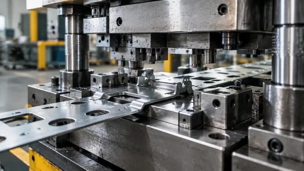
For KT, springback control is not treated as a simple "add more bend" correction. Stable Hardware Stamping requires a coordinated approach involving material properties, part geometry, tooling compensation, press conditions, simulation, tryout data, and production maintenance.
How High-Strength Steel Contributes to More Springback
High-strength steels cause greater springback because more of the deformation occurs elastically.
During Hardware Stamping, sheet metal experiences elastic and plastic deformations. In sheet metal stamping, the plastic deformation remains, and the elastic deformation recovers when the stamping force is removed. High-strength steels are stressed to a higher level than mild steels. Therefore, it is more difficult to predict and control the elastic recovery of the part.
Typical springback defects include:
• Bend angles opening after forming
• Side-wall curl on channel-shaped parts
• Flange movement from nominal position
• Twist across long or asymmetric parts
• Profile deviation after trimming or piercing
The result is often a part that appears correct in the die but fails dimensional inspection after release.
https://youtube.com/shorts/AFAsxcHiA0s?si=uJjMXC5q8Qsy3oxR
Material Parameters That Affect Hardware Stamping Springback
Springback is not controlled by tensile strength alone. For high-strength steel Hardware Stamping, several parameters must be considered together.
| Parameter | Engineering Impact |
| Yield Strength | Higher values generally increase elastic recovery tendency |
| Elastic Modulus | Influences the amount of recoverable elastic strain |
| Sheet Thickness | Affects bending stiffness and springback sensitivity |
| Bend Radius | Works with thickness through the R/t ratio |
| n-value | Influences strain distribution during forming |
| r-value | Indicates directional plastic behavior |
| Rolling Direction | Can change bend response and dimensional consistency |
| Friction | Alters material flow and residual stress distribution |
Why the R/t Ratio Matters
The bend radius-to-thickness ratio is particularly important.
A large R/t generally increases springback tendency because a larger portion of deformation remains elastic. Reducing the bend radius may increase plastic deformation, but it can also increase:
• Local thinning
• Edge cracking
• Surface damage
• Tool load
The correct solution is therefore not simply "use a smaller radius." Geometry must be matched to material strength and forming limits.
Overbend, Restrike and Die Compensation Are Not Interchangeable
Different springback modes require different Hardware Stamping strategies.
| Method | Best Use | Advantage | Limitation |
| Overbend | Predictable angle recovery | Simple and efficient | Weak for complex distortion |
| Restrike | Final angle/profile correction | Strong dimensional control | Adds tooling load or station |
| Die Surface Compensation | Complex 3D shapes | Corrects local geometry | Requires simulation and tryout |
| Process Adjustment | Uneven material flow | Addresses root cause | Needs a stable process window |
Overbend
The die intentionally forms beyond the nominal angle so the part recovers toward specification after unloading.
It is effective for relatively simple, repeatable bend behavior.
Restrike
A secondary calibration operation brings the part closer to its final geometry. In progressive Hardware Stamping, a restrike station can be useful when flange angles or profiles require tighter control.
Die Surface Compensation
For complex AHSS parts, springback may occur as wall curl, twist, or 3D profile distortion. In these cases, local die-surface compensation may be more effective than changing one bend angle.
Control Material Flow Before Correcting Geometry
A common mistake is to modify the die before determining whether springback originates from poor material flow.
KT evaluates process variables such as:
• Blank-holder force
• Draw-bead resistance
• Lubrication
• Forming sequence
• Intermediate forming geometry
• Press motion and forming speed
For example, increasing sheet tension may reduce side-wall curl, but excessive blank-holder force can increase thinning or splitting.
The target is not maximum restraint. It is a repeatable Hardware Stamping process window.
Match Material, Tooling and Press as One System
Changing from mild steel to AHSS affects more than springback.
Higher-strength material can increase:
Forming Load → Tool Contact Stress → Wear → Geometry Drift
A robust Hardware Stamping process must therefore match:
Material → Part Geometry → Tooling → Press → Production Conditions
For KT, this means tooling decisions must consider not only the drawing but also:
• Material grade and thickness
• Critical bend and profile tolerances
• Annual volume
• Tool wear risk
• Station sequence
• Inspection method
KT supports progressive and compound stamping tooling, with published press capacities from 25 to 300 tons. This gives engineers flexibility to match tooling and press capacity to different part sizes and forming loads.
Simulation Must be Validated via Physical Tryout
FEA can predict the flow of material, thinning, localization of strain, and springback prior to final tool adjustment.
Useful input data may include:
• Yield strength
• Stress-strain curve
• Elastic modulus
• n-value
• r-value
• Sheet thickness
• Material direction
However, nominal material data alone is not enough.
Real coil material may vary in:
• Yield strength
• Thickness
• Surface condition
• Work-hardening behavior
For this reason, KT's preferred engineering loop is:
Simulation → Tool Tryout → Measurement → Compensation → Revalidation
This reduces the risk of relying on theoretical springback values that do not match actual production material.
Tool Wear Can Change Springback During Mass Production
Springback control does not finish after tool approval.
The phenomena of springback occurs when tools repeatedly strike a given section of material. Springback can occur from a number of reasons like the radius of a punch or die, surface finish, lubrication, or alignment.
Important maintenance checks include:
• Punch and die radius wear
• Die alignment
• Shut height
• Lubrication consistency
• Cutting and forming surface condition
• Periodic dimensional verification
For long-run Hardware Stamping projects, gradual geometry drift can indicate tooling wear rather than a sudden material problem.
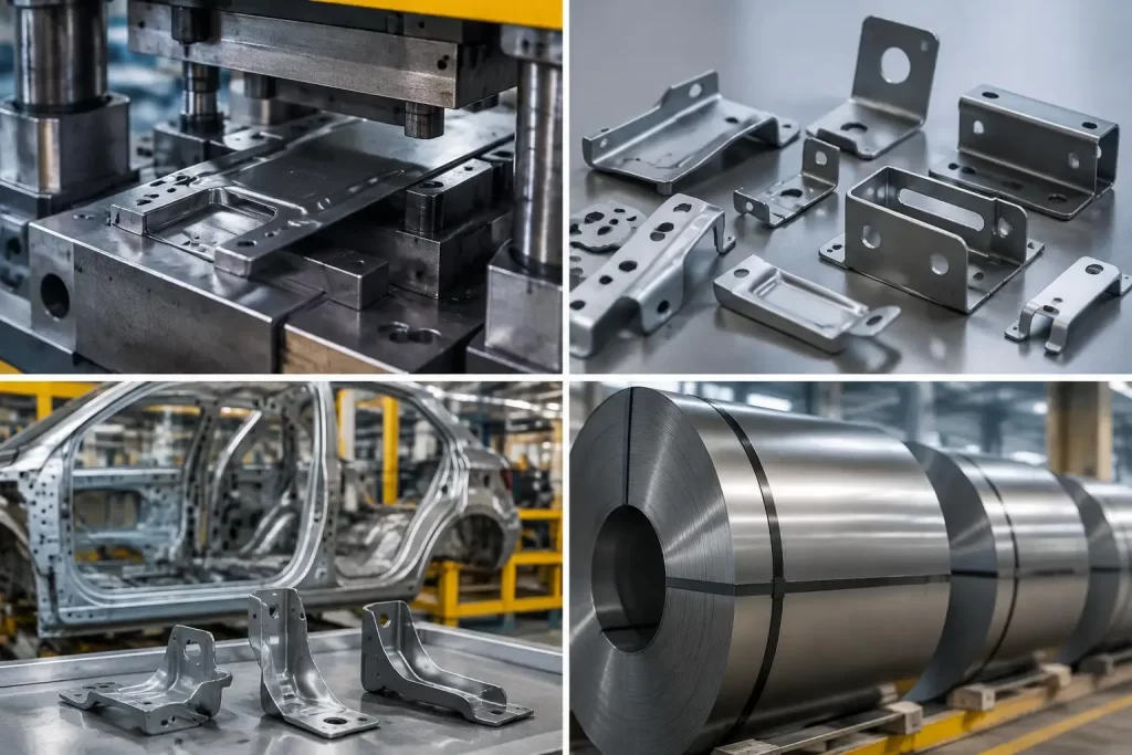
How KT Validates Hardware Stamping Accuracy
A valid process should prove repeatability, not just produce one acceptable sample.
Depending on part geometry, inspection can include:
• Bend angle
• Profile tolerance
• Datum relationships
• Hole-to-edge dimensions
• Flange position
• Overall dimensional stability
KT offers linear stamping tolerances in the range of ±0.01 to ±0.1 mm and angular tolerances from ±0.1° to ±1°, depending on part geometry and production requirements.
These figures should not be treated as universal values for every high-strength steel part. Actual achievable tolerance still depends on:
Material + Geometry + Tool Design + Process Stability + Inspection Method
What Buyers Should Confirm Before Ordering Hardware Stamping Parts
For high-strength steel projects, buyers should provide:
• 2D drawing and 3D model
• Material grade
• Sheet thickness
• GD&T requirements
• Critical bend and profile tolerances
• Surface treatment
• Production volume
• PPAP or inspection requirements
They should also ask the supplier how springback is predicted, compensated, measured, and controlled over tool life.
That is the difference between receiving a stamped part that passes first-article inspection and building a Hardware Stamping process that remains stable in mass production.
For projects involving AHSS, difficult bend geometry, progressive dies, or tight dimensional control, KT can review the part geometry, material specification, and tooling requirements before production.
FAQs
Q1. What Hardware Stamping services does KT provide?
KT supports custom Hardware Stamping, including progressive die, compound die, and single-die stamping. Its capabilities are suited to brackets, connectors, hardware components, and other precision stamped metal parts.
Q2. Can KT manufacture progressive stamping dies?
Yes. KT designs and manufactures progressive stamping dies for applications requiring multiple forming, piercing, bending, and cutting operations within a continuous production sequence.
Q3. What materials can KT use for Hardware Stamping?
KT offers materials including stainless steel, aluminum, brass, and carbon steel for stamping applications. Material selection should also consider strength, formability, thickness, surface condition, and final tolerance requirements.
Q4. Can KT stamp high-strength steel parts?
KT offers high-strength steel for automotive progressive stamping applications. For parts with significant springback risk, the final tooling strategy should be evaluated according to material grade, thickness, bend geometry, and dimensional requirements.
Q5. What tolerance can KT achieve for stamped parts?
KT's typical stamping tolerances around ±0.01–0.05 mm for certain stamping applications, while its broader tolerance guidance lists metal stamping tooling around ±0.05 mm typical and ±0.02 mm for higher-precision applications. Actual tolerance depends on geometry, material, forming sequence, and tooling strategy.
Talk to the Manufacturer, Not a Middleman
Resources & Insights
-
 Industry Insights
CNC Machining Robotic Parts: How GD&T Controls Robot Assembly Accuracy
2026-09-24By KT Engineering -
 Industry Insights
Hardware Stamping Springback Control for High-Strength Steel Parts
2026-09-24By KT Engineering -
 Industry Insights
Spring Stamping Fatigue Life: How Geometry, Material and Edge Quality Affect Cycle Life
2026-09-24By KT Engineering -
 Industry Insights
Mechanical Automation Parts for Robot End Effectors and Positioning Accuracy
2026-09-23By KT Engineering