Contact Us
 Home /
CNC Machining Robotic Parts: How GD&T Controls Robot Assembly Accuracy


Table of Contents
- Why Dimensionally Correct Robotic Parts Can Still Misalign
- Which GD&T Controls Matter Most for Robotic Parts?
- ± Tolerance vs. GD&T for Robot Joint Housings
- Position, Runout, or Profile?
- MMC/MMR Can Improve Assembly Without Excessive Tolerances
- How GD&T Errors Accumulate Across Robot Joints
- Machining Strategy Matters as Much as the Drawing
- Assembly Can Destroy Good Machining Accuracy
- How Should CNC Machining of Robotic Parts Be Verified?
- What Buyers Should Confirm Before Ordering

A robotic joint can contain several CNC Machining Robotic Parts that individually pass dimensional inspection yet still bind, wobble, or require adjustment during assembly. The reason is simple: a correct diameter or length does not guarantee that a bore, mounting face, shaft axis, or bolt pattern is geometrically located and oriented correctly.
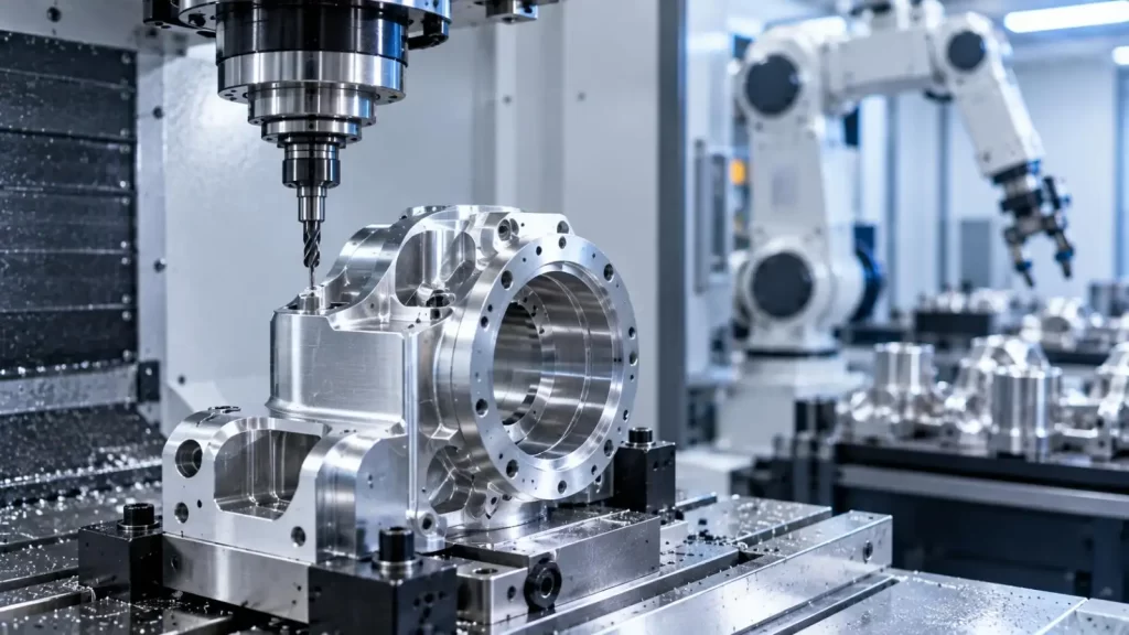
For robot joint housings, actuator bodies, bearing seats, motor mounts, and output flanges, GD&T (Geometric Dimensioning and Tolerancing) connects machining accuracy to functional assembly.
Why Dimensionally Correct Robotic Parts Can Still Misalign
Consider a joint housing with two bearing bores. Both bores may satisfy their diameter tolerance, but the assembly can still fail if their axes are offset or angularly misaligned.
The same applies to a gearbox mounting flange. Good flatness alone does not guarantee that its functional axis is perpendicular to the mounting face.
This distinction is critical in CNC Machining Robotic Parts:
Part size → Geometric relationship → Joint alignment → Multi-axis tolerance stack-up → Robot performance
Robot positioning accuracy should therefore never be inferred directly from a statement such as "the machined part is ±0.01 mm." Gearbox backlash, bearing behavior, encoder accuracy, structural deflection, calibration, and thermal effects also influence final robot performance.
Which GD&T Controls Matter Most for Robotic Parts?
Instead of applying extremely tight ± tolerances everywhere, engineers should identify the features that locate or transmit motion.
| Robotic Feature | Important GD&T Control | Main Functional Risk |
| Bearing bore | Position, cylindricity, perpendicularity | Shaft or bearing misalignment |
| Output flange | Runout, perpendicularity | Flange wobble |
| Dowel holes | Position | Repeatable assembly error |
| Bolt pattern | Position | Difficult assembly |
| Mounting face | Flatness | Uneven seating |
| Opposing bearing seats | Position / orientation | Axis mismatch |
| Complex housing surface | Profile | Interface mismatch |
The datum system is especially important. A datum should represent how the CNC Machining Robotic Parts actually locate in the robot—not simply whichever surface is easiest to measure.
For example, the primary datum may be a gearbox mounting face in one design but a precision locating bore in another.
± Tolerance vs. GD&T for Robot Joint Housings
Traditional coordinate tolerancing and GD&T answer different questions.
| Requirement | ± Coordinate Tolerance | GD&T |
| Control bore diameter | Good | Good |
| Locate a bolt pattern | Possible but restrictive | Position is usually clearer |
| Control bearing-axis orientation | Limited | Strong |
| Reference functional interfaces | Limited | Datum system |
| Control rotating interfaces | Weak | Runout |
| Protect assembly function | Limited | Stronger functional definition |
This is why specifying every dimension at ±0.005 mm is not automatically a better solution. It can increase machining and inspection cost while failing to control the geometry that actually causes assembly problems.
Position, Runout, or Profile?
Selecting the correct control depends on function.
Position is commonly relevant to bearing axes, dowel holes, and bolt patterns. Runout becomes important when a shaft, hub, or output flange rotates around a functional datum axis. Profile can control complex machined housing surfaces where several connected surfaces must remain within a defined boundary.
Form controls such as cylindricity address a different problem again: a bearing bore may be correctly located but still have poor form.
For this reason, a drawing for CNC Machining Robotic Parts should not treat GD&T symbols as interchangeable methods of "adding precision."
MMC/MMR Can Improve Assembly Without Excessive Tolerances
Bolt and locating-hole patterns illustrate why geometric tolerancing can be more economical than universally tight dimensions.
Under maximum material principles, the permissible geometric variation can relate to actual feature size while preserving the functional assembly boundary. ISO 2692:2021 specifically identifies assembly of parts as an application of the maximum material requirement.
This can be useful for robotic housings with multiple fasteners because manufacturing freedom can increase without sacrificing guaranteed fit.
However, MMC/MMR should be applied only when the feature function supports it—not simply to enlarge tolerances.
How GD&T Errors Accumulate Across Robot Joints
A robot arm does not contain one isolated precision component. Its geometry forms a chain:
Bearing axis → Gearbox axis → Output flange → Next link → Next joint axis
A small orientation error at one interface may therefore affect downstream alignment differently from a simple linear dimensional error.
This makes tolerance-stack analysis especially important for multi-axis robots, collaborative robots, and compact actuator modules.
The design objective should be to control the interfaces that define each joint coordinate system rather than assign unnecessarily tight tolerances to every machined surface.
Machining Strategy Matters as Much as the Drawing
Correct GD&T must be supported by a manufacturing process capable of preserving datum relationships.
For CNC Machining Robotic Parts, useful process strategies include:
•Machining multiple critical faces in one setup where practical;
•Minimizing datum transfer between setups;
•Controlling clamping distortion on thin-wall aluminum housings;
•Separating roughing and precision finishing when residual stress is significant;
•Verifying critical bore, flange, and locating relationships from the drawing datum structure.
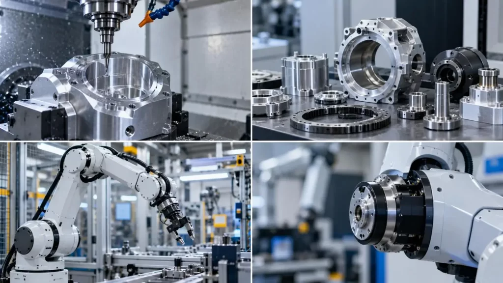
Five-axis machining can be valuable when several functional surfaces must be reached without repeated repositioning. KT states that its CNC operation includes 3-, 4-, and 5-axis equipment, with simultaneous 5-axis capability for complex multi-surface parts. Its CNC page lists tolerances down to ±0.001 mm on selected critical features, depending on the application, and more than 70 CNC centers.
KT also offers a robotic main-joint housing example produced from 7075 aluminum by 5-axis CNC machining with a dimensional tolerance of ±0.025 mm, illustrating why realistic tolerances should be assigned according to the specific component rather than one universal number.
https://youtube.com/shorts/azN1Gm4ptvs?feature=share
Assembly Can Destroy Good Machining Accuracy
Precision machining alone cannot protect a robotic joint from poor assembly.
Damaged bearing seating surfaces, part contamination, distortion of housings, variable tightening of bolts, and damaged or missing dowels are examples of problems that can occur during bearing installation. All of these issues can lead to unpredictable changes to the machined part geometry.
After replacing gears or bearings, surfaces for locating should be checked to determine if their seating is adequate. The condition of bolts, flange runout, and calibration of joints may all also need to be evaluated.
How Should CNC Machining of Robotic Parts Be Verified?
CMM inspection can measure positional datums, orientational datums, and profile as well as datum-related issues that are complex. Using a specialized fixture may prove useful for some cylindrical features. For repetitive production interfaces, functional gauges may also prove efficient.
Most importantly, the inspection setup should be designed to represent the datum logic of the engineering drawing.
ASME Y14.5-2018 (R2024) is the ASME reference for GD&T and ISO 5459:2024 describes the terminology and methodology of datums within the datum systems of ISO GPS.
KT's CNC process includes CMM inspection and material traceability and is able to support verifications throughout the processes of prototype development and production.
What Buyers Should Confirm Before Ordering
Before releasing CNC Machining Robotic Parts, buyers should align the supplier on the GD&T standard and edition, functional datum scheme, bearing and shaft fits, critical characteristics, inspection method, first-article requirements, material, surface treatment, expected production volume, and required dimensional reports.
The most capable supplier is not necessarily the one advertising the smallest tolerance number. It is the supplier that understands which dimensions and geometric relationships control the robot’s function and can manufacture and measure them consistently.
For robot joint housings, actuator components, precision shafts, and other complex CNC Machining Robotic Parts, KT combines multi-axis CNC machining, engineering review, and dimensional inspection. Engineers developing a new robotic assembly can submit 2D drawings or 3D models through KT CNC Machining to review machining strategy and critical tolerance requirements before moving from prototype to production.
FAQs
Q1. What CNC Machining Robotic Parts can KT manufacture?
KT can support precision robotic components such as joint housings, actuator housings, mounting brackets, shafts, bearing seats, motor interfaces, flanges, and other complex CNC-machined structural parts.
Q2. Does KT provide 5-axis machining for robotic parts?
Yes. KT provides 3-axis, 4-axis, and 5-axis CNC machining, making it suitable for robotic parts with multiple precision surfaces, angled features, complex bores, and tight datum relationships.
Q3. How does KT control GD&T requirements on robotic components?
KT can manufacture parts according to customer drawings that specify datums, position, perpendicularity, parallelism, profile, runout, and other GD&T requirements, with inspection based on the defined functional references.
Q4. What machining tolerance can KT achieve for CNC Machining Robotic Parts?
KT's machining capability is down to ±0.001 mm for selected critical features, depending on part geometry, material, feature size, process, and inspection requirements. Robotic parts should therefore be evaluated individually rather than assigned one universal tolerance.
Q5. Can KT machine robotic joint housings from aluminum?
Yes. Aluminum alloys are commonly used for lightweight robotic housings and structural components. KT has also offers a 7075 aluminum robotic main-joint housing produced using 5-axis CNC machining.
Talk to the Manufacturer, Not a Middleman
Resources & Insights
-
 Industry Insights
CNC Machining Robotic Parts: How GD&T Controls Robot Assembly Accuracy
2026-09-24By KT Engineering -
 Industry Insights
Hardware Stamping Springback Control for High-Strength Steel Parts
2026-09-24By KT Engineering -
 Industry Insights
Spring Stamping Fatigue Life: How Geometry, Material and Edge Quality Affect Cycle Life
2026-09-24By KT Engineering -
 Industry Insights
Mechanical Automation Parts for Robot End Effectors and Positioning Accuracy
2026-09-23By KT Engineering