Contact Us
 Home /
Mechanical Automation Parts for Robot End Effectors and Positioning Accuracy


Table of Contents
- Why End-Effector Weight Becomes a Positioning Problem
- Where Mechanical Error Enters the TCP
- Material Selection: Strength Is Not Stiffness
- Solid, Pocketed or Ribbed Mechanical Automation Parts?
- 3-Axis vs. 5-Axis Machining for EOAT Components
- Match Mechanical Automation Parts to the Robot System
- Installation and Maintenance Can Reintroduce Error
- Verify Geometry Before Approving Production
- What to Include in a Mechanical Automation Parts RFQ

Robot end effectors sit at the end of the kinematic chain, where machining tolerance, structural stiffness and payload dynamics directly affect the tool center point (TCP). For Mechanical Automation Parts used in grippers, adapter plates, sensor mounts and robot joints, “lightweight” is not enough. The part must remain stiff under load, locate repeatably after assembly and stay within robot payload, moment and inertia limits.
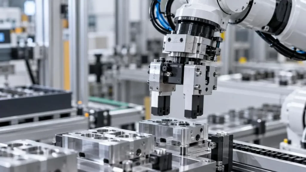
At KT, the engineering question is not only whether a part can be machined, but whether the Mechanical Automation Parts can maintain critical geometry after machining, assembly and dynamic loading.
Why End-Effector Weight Becomes a Positioning Problem
The robot sees the complete wrist load: gripper, adapter, fasteners, sensors, cables and workpiece.
Moment = Force × Distance from the Wrist
Deflection ∝ FL³ / EI
The first explains why center of gravity matters. A light component far from the flange can create a large wrist moment. The second explains why long gripper fingers are difficult: unsupported length has a cubic effect on bending deflection.
For Mechanical Automation Parts, weight reduction should remove low-stress material while preserving load paths and section depth.
Where Mechanical Error Enters the TCP
Robot repeatability and end-effector accuracy are not the same. A robot can repeatedly return to the same joint position while the TCP still shifts because of:
• Flange flatness error
• Dowel-hole position variation
• Jaw parallelism error
• Adapter bending
• Bolt-clearance movement
• Bearing or bushing play
• Thermal expansion
• Gripper finger deflection
A ±0.01 mm machined feature does not guarantee ±0.01 mm TCP accuracy. The real result is a tolerance-and-stiffness chain from the robot wrist to the contact point.
For critical Mechanical Automation Parts, use functional datums and GD&T for location, orientation and form instead of tightening every dimension.
Material Selection: Strength Is Not Stiffness
| Material | Weight | Strength | Relative Stiffness | Typical EOAT Use |
| 6061-T6 Aluminum | Low | Medium | Medium | Plates, brackets, housings |
| 7075-T6 Aluminum | Low | High | Medium | High-load lightweight parts |
| Stainless Steel | High | High | High | Pins, wear zones, rigid inserts |
| PEEK | Very Low | Lower | Lower | Insulating lightweight parts |
A common mistake is selecting 7075 because it is assumed to be much stiffer than 6061. Its strength is higher, but its elastic modulus is not proportionally higher.
If deflection controls performance, increasing section depth, adding ribs or shortening overhang may improve the Mechanical Automation Parts more effectively than simply changing aluminum grade.
Solid, Pocketed or Ribbed Mechanical Automation Parts?
| Structure | Weight | Rigidity | Main Risk |
| Solid Section | High | High | Excess mass/inertia |
| Deep Pocketing | Low | Can fall sharply | Thin-wall distortion |
| Ribbed Structure | Low-Medium | High if optimized | More DFM-sensitive |
Good lightweighting does not mean maximum pocket depth. A practical DFM review should check:
• Rib direction versus load
• Unsupported spans
• Wall-thickness consistency
• Tool access and corner radii
• Clamping deformation
• Post-machining distortion
The objective is a better stiffness-to-mass ratio, not simply lower mass.
3-Axis vs. 5-Axis Machining for EOAT Components
Simple Mechanical Automation Parts such as flat adapter plates may be more economical on 3-axis machines. Complex end-effector parts often combine angled faces, precision bores, dowel locations and mounting surfaces across several planes.
| Factor | Multi-Setup 3-Axis | 5-Axis |
| Re-clamping | More | Less |
| Datum Transfer | More frequent | Reduced |
| Angled Features | More difficult | Direct access |
| Best Fit | Simple geometry | Complex multi-face parts |
The value of 5-axis machining is not that every dimension becomes automatically tighter. Its key advantage is reducing repositioning between related features.
KT's 5-axis centers can mill, drill, tap and machine angled holes in one setup. Its process includes DFM review and CMM inspection of first articles. KT also publishes ±0.005 mm capability on selected precision-machined parts, depending on geometry, material and process conditions.
Match Mechanical Automation Parts to the Robot System
Before releasing an end-effector design, verify:
• Total EOAT and workpiece mass
• Center of gravity in X/Y/Z
• Maximum wrist moment
• Allowable moment of inertia
• Required acceleration
• TCP stability requirement
A dimensionally correct part can still be unsuitable if its mass distribution or stiffness exceeds the robot's dynamic limits.
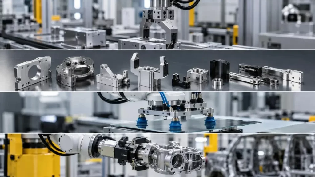
This is why Mechanical Automation Parts should be evaluated as part of the complete robotic system, not as isolated CNC components.
Installation and Maintenance Can Reintroduce Error
Even precision Mechanical Automation Parts can lose repeatability after installation.
Key controls include:
• Clean datum and mounting faces
• Controlled bolt tightening
• Dedicated locating features for repeatable removal
• Inspection of dowel pins and interfaces
• TCP recalibration after mechanical changes
For high-cycle tooling, engineers should separate robot calibration drift from loosened fasteners, worn locating features or structural deformation.
Verify Geometry Before Approving Production
KT's automation manufacturing process lists CMM inspection, optical comparison, material traceability and a reported production pass rate of ≥99.8%.
For critical Mechanical Automation Parts, inspection should cover:
• Datum relationships
• True position of locating holes
• Flatness and parallelism
• Perpendicularity
• Critical fits
• Runout on rotational interfaces
CMM acceptance confirms that a part matches the drawing. It does not replace functional validation under representative load.
What to Include in a Mechanical Automation Parts RFQ
A useful RFQ should provide:
• 2D drawings and 3D CAD
• Material and quantity
• Critical datums and GD&T
• Mating-component information
• Load direction and payload
• Surface treatment
• Inspection requirements
• Prototype and production expectations
The best Mechanical Automation Parts are not simply the lightest or tightest-tolerance components. They are parts whose mass distribution, rigidity, interfaces, machining route and verification plan match the robot as a complete mechanical system.
KT manufactures automation components including end effectors, clamps, actuators, sensors, joints, linkages and housings from prototype through scalable production. Sharing drawings and operating requirements early allows the KT engineering team to review manufacturability, datum strategy, machining route and inspection requirements before production.
FAQs
Q1. What Mechanical Automation Parts can KT manufacture?
KT manufactures custom Mechanical Automation Parts such as robot end-effector components, clamps, actuator parts, sensor mounts, joints, linkages, housings, brackets, adapter plates and precision locating components.
Q2. Can KT manufacture lightweight robot end-effector parts?
Yes. KT can machine aluminum alloys and engineering plastics for lightweight Mechanical Automation Parts, while DFM review can help balance mass reduction with structural rigidity and machinability.
Q3. What materials does KT use for Mechanical Automation Parts?
Common materials include 6061 and 7075 aluminum, stainless steel, carbon steel and engineering plastics such as PEEK. Material selection depends on weight, strength, stiffness, wear and operating environment.
Q4. What machining tolerance can KT achieve for automation parts?
KT's precision CNC machining capability down to approximately ±0.005 mm for selected parts, depending on geometry, material, feature size and machining conditions.
Q5. Does KT provide 5-axis CNC machining for robot end-effector components?
Yes. KT uses 5-axis machining for complex Mechanical Automation Parts with multi-face features, angled holes, precision bores and related datum surfaces that may otherwise require multiple setups.
Talk to the Manufacturer, Not a Middleman
Resources & Insights
-
 Industry Insights
CNC Machining Robotic Parts: How GD&T Controls Robot Assembly Accuracy
2026-09-24By KT Engineering -
 Industry Insights
Hardware Stamping Springback Control for High-Strength Steel Parts
2026-09-24By KT Engineering -
 Industry Insights
Spring Stamping Fatigue Life: How Geometry, Material and Edge Quality Affect Cycle Life
2026-09-24By KT Engineering -
 Industry Insights
Mechanical Automation Parts for Robot End Effectors and Positioning Accuracy
2026-09-23By KT Engineering