Contact Us
 Home /
Machining Component Inspection: CMM vs. On-Machine Measurement


Table of Contents
- Why One Machining Component Can Produce Two Different Measurement Results
- CMM vs. On-Machine Measurement: Define the Inspection Objective First
- Different Features Require Different Measurement Strategies
- Why ±0.005 mm Requires More Than a Good CNC Machine
- Clamping Can Hide Machining Component Deformation
- Prototype, FAI, and Production Should Not Use the Same Inspection Plan
- Measurement Strategy Must Follow the Drawing Datum Structure
- Inspection Equipment Also Requires Process Control

For a precision Machining Component, machining to size is only part of the quality requirement. The manufacturer must also prove that critical dimensions, GD&T characteristics, fits, and functional interfaces conform to the drawing under a controlled inspection method.
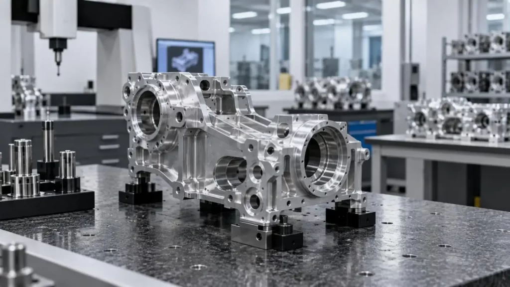
This becomes increasingly important when a Machining Component contains tolerances such as ±0.01 mm or ±0.005 mm, multi-datum positioning, thin walls, deep bores, or complex 5-axis geometry.
At KT, we treat CMM inspection and on-machine measurement as two different layers of process control rather than interchangeable inspection technologies.
The key question is not simply:
"Which system is more accurate?"
It is:
Which system should measure each feature, at which production stage, and for what acceptance purpose?
Why One Machining Component Can Produce Two Different Measurement Results
A Machining Component may measure within tolerance on the CNC machine but show a different result during final CMM inspection.
This can happen because on-machine measurement includes more variables in the measurement chain.
Typical On-Machine Error Sources
• Machine-axis geometric error
• Thermal growth of machine structure
• Probe calibration condition
• Tool or spindle temperature
• Fixture deformation
• Workpiece clamping force
• Datum reconstruction
• Stylus length and approach direction
• Material temperature
A probe with high repeatability does not automatically make the CNC machine a high-accuracy CMM.
For a precision Machining Component, the real measurement result is influenced by the complete system:
Probe + CNC Geometry + Thermal Condition + Fixture + Datum Strategy + Calibration + Measurement Method
This is why probe repeatability and total measurement accuracy should never be treated as the same specification.
CMM vs. On-Machine Measurement: Define the Inspection Objective First
The two systems solve different production problems.
| Inspection Factor | CMM | On-Machine Measurement |
| Primary role | Independent verification | Process control |
| Measurement timing | After machining | During machining |
| Tool offset correction | No | Immediate |
| CNC geometric influence | Minimal | Significant |
| Complex GD&T capability | High | Application-dependent |
| Production response | Slower | Fast |
| Typical use | FAI, final inspection, audit | Setup, drift detection, compensation |
For KT, on-machine measurement is most valuable when the Machining Component can still be corrected.
For example, probing can help identify:
• Hole-position drift
• Tool-length variation
• Bore-size deviation
• Workpiece misalignment
• Datum shift
• Progressive tool wear
The CNC process can then be adjusted before additional nonconforming parts are produced.
CMM inspection serves a different purpose: verifying the finished Machining Component independently from the manufacturing machine.
https://youtube.com/shorts/eLQHl614qXM?feature=share
Different Features Require Different Measurement Strategies
A professional inspection plan should not send every dimension to the CMM.
The method should be selected according to tolerance, geometry, functional risk, datum dependence, and production volume.
| Machining Component Feature | Typical Inspection Method | Main Reason |
| External diameter | Micrometer / CMM | Fast dimensional verification |
| Bore diameter | Bore gauge / probe / CMM | Size and fit control |
| Hole position | CMM / validated OMM | Datum-dependent geometry |
| Depth | Probe / CMM | Efficient process monitoring |
| Flatness | CMM / suitable metrology | Form verification |
| Surface profile | CMM scanning | High data density |
| Multi-datum GD&T | CMM | Coordinate-based evaluation |
| Tool-wear-sensitive dimension | OMM + periodic CMM | Process drift control |
This feature-based approach avoids two common problems: over-inspecting simple dimensions and under-inspecting critical geometry.
Why ±0.005 mm Requires More Than a Good CNC Machine
KT supports standard CNC tolerances around ±0.05 mm and high-precision Machining Component production down to approximately ±0.005 mm depending on material, geometry, equipment, and process conditions.
At this level, dimensional control becomes a system-engineering issue.
Critical Variables Include
• Machine thermal stability
• Tool runout and wear
• Material residual stress
• Workholding stiffness
• Cutting-force deformation
• Datum repeatability
• Inspection uncertainty
• Part temperature during measurement
A reading of 25.003 mm does not automatically mean a dimension is safely acceptable if the upper specification limit is close to that value.
The manufacturer must also consider the capability of the measurement system and the uncertainty associated with the result.
For this reason, tight-tolerance Machining Component inspection should never be based only on a displayed measurement number.
Clamping Can Hide Machining Component Deformation
One of the most important differences between on-machine and post-process inspection is the physical state of the part.
A Machining Component measured while clamped may not have the same geometry after removal from the fixture.
This is especially important for:
• Thin-wall aluminum housings
• Large machined plates
• Ring-shaped components
• Long slender parts
• Pocketed aerospace structures
• Low-stiffness plastic components
Excessive clamping force may temporarily flatten or constrain the workpiece.
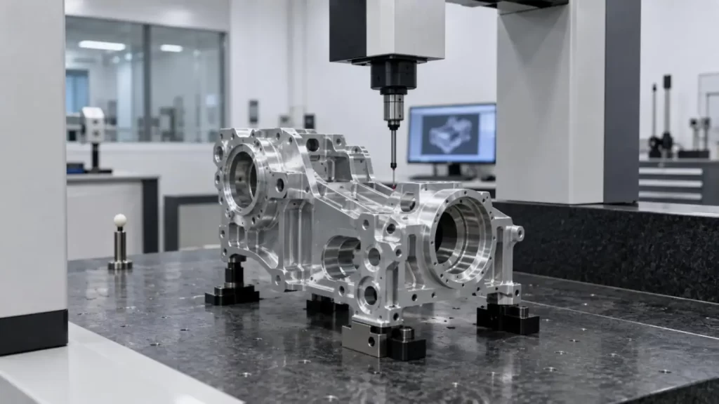
After release, residual stress and elastic recovery can change:
• Flatness
• Parallelism
• Bore geometry
• Wall position
• Overall profile
For these parts, KT evaluates not only machining accuracy but also fixture strategy, machining sequence, material behavior, and final inspection condition.
Prototype, FAI, and Production Should Not Use the Same Inspection Plan
Inspection requirements change as the project moves toward volume production.
Prototype Stage
The goal is to expose design and manufacturing risks.
Useful checks include:
• Full dimensional review
• Datum verification
• Critical GD&T inspection
• Fit and interface dimensions
• Difficult-to-machine features
First Article Inspection
The first article should confirm whether the entire manufacturing route can produce the required Machining Component repeatedly.
This is where CMM inspection is particularly valuable for validating datum structure and complex geometry.
Production Stage
The focus shifts toward process stability.
A practical control loop may be:
Machine Setup → On-Machine Probe → Cutting → Critical Feature Check → Offset Correction → Periodic CMM Verification → Final Inspection
This hybrid approach reduces the risk of discovering dimensional drift only after an entire batch has been completed.
Measurement Strategy Must Follow the Drawing Datum Structure
For complex Machining Component inspection, datum strategy often matters more than the number of measurement points.
If manufacturing and inspection use different datum references, two apparently correct measurements may not describe the same geometric condition.
This becomes critical for:
• True position
• Perpendicularity
• Parallelism
• Profile
• Runout
• Multi-hole patterns
For 4-axis and 5-axis Machining Component production, KT focuses on reducing unnecessary re-clamping because every additional setup introduces another opportunity for datum transfer error.
Where practical, multi-surface machining in fewer setups can improve positional consistency before the part reaches final inspection.
Inspection Equipment Also Requires Process Control
CMMs and CNC probes are not automatically reliable simply because they are high-end instruments.
Verification should be considered after:
• Probe stylus replacement
• Probe collision
• CNC crash
• Machine maintenance
• Fixture replacement
• Significant thermal changes
• Suspected dimensional drift
A stable inspection system also requires controlled procedures for:
• Probe qualification
• Datum alignment
• Measurement programs
• Gauge calibration
• CMM verification
• Inspection record control
The appropriate interval should be determined by production risk, equipment recommendations, customer requirements, and the applicable quality system.
Build Machining Component Inspection Around Risk
There is no single inspection technology that is ideal for every Machining Component.
On-machine measurement is strongest when the objective is to detect process drift and make corrections while machining is still active. CMM inspection is strongest when independent verification of dimensions and GD&T is required. Manual gauges remain effective for many straightforward characteristics.
KT combines 3-axis, 4-axis, and 5-axis CNC machining, in-process control, post-process dimensional inspection, and high-precision machining capability down to approximately ±0.005 mm where geometry, material, and process conditions permit.
For a Machining Component with tight tolerances, complex GD&T, difficult workholding, or critical fit requirements, the inspection strategy should ideally be reviewed before production begins—not after parts are already machined.
You can send your drawing or 3D model to KT to evaluate the machining route, tolerance risks, and suitable inspection approach before moving into production.
FAQs
Q1. How does KT inspect a precision Machining Component?
KT combines in-process measurement, dimensional gauges, and post-process inspection methods such as CMM according to the Machining Component geometry, tolerance, GD&T requirements, and production stage.
Q2. Can KT manufacture a Machining Component to ±0.005 mm tolerance?
KT supports high-precision CNC machining down to approximately ±0.005 mm for suitable components. Achievable tolerance depends on material, geometry, feature size, workholding, and machining conditions.
Q3. Does KT use CMM inspection for every Machining Component?
Not necessarily. CMM inspection is generally more valuable for critical dimensions, complex GD&T, first article verification, and high-risk features. Simpler dimensions may be inspected with appropriate calibrated gauges.
Q4. Does KT use on-machine probing during CNC machining?
KT applies in-process measurement and probing where appropriate to verify setup conditions, monitor critical features, detect dimensional drift, and support machining corrections before final inspection.
Q5. Can on-machine measurement replace CMM inspection at KT?
Not in every application. On-machine measurement is mainly useful for process control, while CMM inspection provides more independent verification of finished Machining Component dimensions and complex GD&T characteristics.
Talk to the Manufacturer, Not a Middleman
Resources & Insights
-
 Industry Insights
CNC Machining Robotic Parts: How GD&T Controls Robot Assembly Accuracy
2026-09-24By KT Engineering -
 Industry Insights
Hardware Stamping Springback Control for High-Strength Steel Parts
2026-09-24By KT Engineering -
 Industry Insights
Spring Stamping Fatigue Life: How Geometry, Material and Edge Quality Affect Cycle Life
2026-09-24By KT Engineering -
 Industry Insights
Mechanical Automation Parts for Robot End Effectors and Positioning Accuracy
2026-09-23By KT Engineering