Contact Us
 Home /
Rapid Prototyping Surface Finish: Ra, Anodizing, Sandblasting and Powder Coating


Table of Contents
- Why Surface Finish Must Be Defined Early in Rapid Prototyping
- Ra Is Important, But It Does Not Fully Define Surface Quality
- As-Machined vs. Sandblasted Surfaces
- Direct Anodizing vs. Sandblast + Anodizing
- Type II vs. Hard Anodizing
- Anodizing vs. Powder Coating
- Match the Finish to the Prototype Objective
- Final Inspection Must Be Performed After Finishing
- What to Include in a Rapid Prototyping RFQ

In Rapid Prototyping, dimensional accuracy is only one part of functional validation. A prototype can meet the drawing after CNC machining and still fail during assembly, sealing, sliding, or cosmetic evaluation once anodizing, sandblasting, or powder coating is applied.
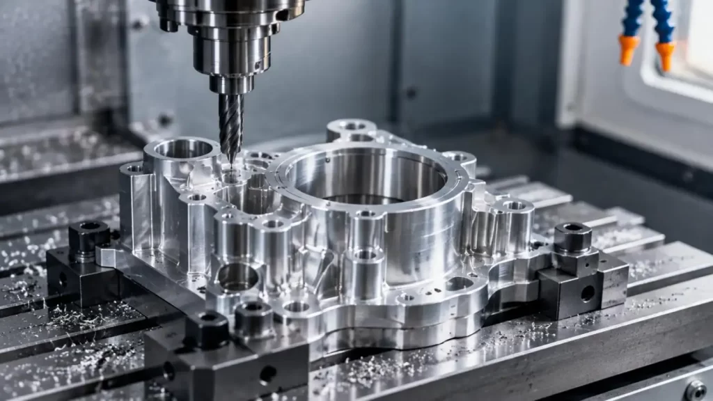
At KT, surface finishing is therefore considered part of the Rapid Prototyping manufacturing chain, not simply a cosmetic step added after machining.
The practical engineering sequence is:
Machining → Surface Roughness → Pretreatment → Final Finish → Dimensional Change → Assembly → Final Inspection
Understanding this sequence helps engineers avoid one of the most common prototype problems: a component that looks correct but no longer fits or performs as intended after finishing.
Why Surface Finish Must Be Defined Early in Rapid Prototyping
A machined prototype may include several completely different surface functions:
•Cosmetic exterior surfaces
•Bearing or shaft interfaces
•Threaded holes
•Sealing faces
•Press-fit locations
•Electrical grounding areas
•Sliding surfaces
Applying the same treatment to every face is rarely the best engineering solution.
For example, KT's Rapid Prototyping CNC capability typically supports tolerances around ±0.05–0.1 mm, depending on geometry, material, feature size, and process requirements. When a critical fit is already near the tolerance limit, any subsequent coating or surface conversion must be considered before production starts.
This is especially important for:
•Precision bores
•Threaded features
•Locating pins
•Bearing seats
•Mating flanges
•Enclosure interfaces
The correct question is not simply, "Which finish should we use?" It is:
Which surfaces require finishing, which must remain dimensionally controlled, and which need masking?
Ra Is Important, But It Does Not Fully Define Surface Quality
Ra represents the arithmetic average deviation of a surface profile. It is useful, but it should not be treated as a complete description of surface quality.
Two Rapid Prototyping parts can have similar Ra values while showing visibly different:
•Cutter marks
•Feed lines
•Surface lay
•Scratches
•Tool-path transitions
•Reflected light patterns
KT offers a standard as-machined CNC surface around 125 μin Ra, approximately 3.2 μm Ra, for typical CNC milling conditions.
However, a lower Ra does not automatically mean a better prototype.
For a bearing seat, sealing surface, or sliding feature, roughness may directly affect function. For an external enclosure, visual uniformity may matter more than achieving an unnecessarily low numerical Ra.
A More Practical Surface Definition
Instead of calling everything Ra, divide it into:
•Functional surfaces: Adjustable for Ra, dimensions, and geometry.
•Cosmetic surfaces: Adjustable for texture, color, and visual uniformity.
•Critical mating surfaces: Adjustable for final dimensions after completing the process.
Following this suggestion only allows time to be spent where it is really needed and improves the reliability of the prototype.
As-Machined vs. Sandblasted Surfaces
Sandblasting or bead blasting is often used in Rapid Prototyping to produce a uniform matte texture before anodizing or as a final cosmetic treatment.
| Parameter | As-Machined | Sandblasted |
| Tool marks | Usually visible | Reduced visually |
| Surface direction | Follows tool path | More uniform |
| Dimensional influence | Minimal | Critical faces require control |
| Appearance | Technical / machined | Matte / uniform |
| Typical use | Functional prototypes | Cosmetic prototypes |
Sandblasting should not be applied indiscriminately.
Features such as:
•Sealing faces
•Precision bores
•Bearing locations
•Press-fit surfaces
•Fine threads
may require masking because the blasting process changes the local surface texture and contact condition.
Direct Anodizing vs. Sandblast + Anodizing
Anodizing does not simply "cover" machining marks. The final appearance depends on the underlying aluminum condition.
Important variables include:
•Aluminum alloy
•Machining direction
•Initial surface roughness
•Scratches
•Blasting condition
•Cleaning and pretreatment
•Anodizing type
This is why two aluminum prototypes can be machined to similar dimensions but look different after anodizing.
For Rapid Prototyping, the choice is usually based on the purpose of the part:
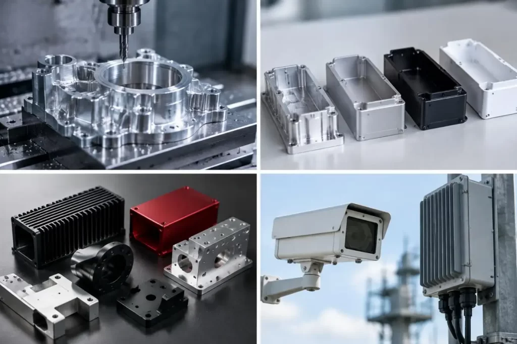
Direct Anodizing
More suitable when:
•Machining texture is acceptable
•Dimensional control has priority
•The prototype is mainly functional
Sandblast + Anodizing
More suitable when:
•Matte appearance is required
•CNC tool marks must be visually reduced
•The prototype is used for design or CMF evaluation
KT supports both blasting and anodizing, allowing the machining condition and final finish to be planned together.
Type II vs. Hard Anodizing
Type II and hard anodizing should not be selected purely by appearance.
| Requirement | Type II Anodizing | Hard Anodizing |
| Primary purpose | Corrosion resistance / appearance | Wear resistance |
| Cosmetic use | Common | Secondary |
| Functional wear testing | Limited | More suitable |
| Dimensional impact | Must be considered | More critical |
| Typical prototype | Housing, cover, bracket | Sliding or wear component |
For precision Rapid Prototyping, anodized surfaces around bearing seats, bores, or mating features may require dimensional allowance or masking.
Anodizing vs. Powder Coating
Powder coating and anodizing solve different engineering problems.
| Decision Factor | Anodizing | Powder Coating |
| Typical material | Aluminum | Various metals |
| Surface type | Oxide conversion layer | Applied coating |
| Color flexibility | Good | Very high |
| Wear option | Hard anodizing available | Depends on system |
| Thickness influence | Moderate | Usually greater |
| Precision fits | Requires planning | Masking often essential |
| Typical application | Precision aluminum parts | Housings, frames, brackets |
Powder coating is useful when a Rapid Prototyping enclosure must simulate production color and environmental protection. However, excessive coating on threads, locating holes, grounding surfaces, or mating interfaces can cause assembly problems.
Match the Finish to the Prototype Objective
There is no universal best finish.
A more effective selection method is:
| Prototype Objective | Recommended Strategy |
| Dimensional verification | As-machined |
| Visual appearance review | Blast + decorative finish |
| Wear testing | Hard anodizing |
| Housing validation | Powder coating |
| CMF validation | Production-intent finish |
| Assembly testing | Selective finishing + masking |
The finish should therefore be selected according to what the Rapid Prototyping part must actually prove.
Final Inspection Must Be Performed After Finishing
Inspection should not end after CNC machining.
KT recommends defining the final inspection condition according to the drawing and finish specification, especially for critical dimensions.
A complete inspection plan may include:
•Final dimensional verification
•Surface roughness measurement
•Coating or anodizing requirements
•Color and cosmetic acceptance
•Masked-area confirmation
•Critical fit verification
Surface texture may be specified using the ISO 21920 series, while anodized aluminum may reference standards such as ISO 7599 or ISO 10074 when required by the application.
The important principle is simple:
Machining inspection confirms the part before finishing. Final inspection confirms whether the finished prototype still meets its functional requirement.
What to Include in a Rapid Prototyping RFQ
To reduce quotation ambiguity, include:
•Material and alloy
•Drawing and 3D model
•Required Ra on critical surfaces
•Finish type
•Anodizing or coating requirement
•Color and gloss level
•Masking locations
•Cosmetic surfaces
•Critical dimensions
•Threads and mating features
•Inspection requirements
•Prototype quantity
KT combines CNC machining, 3D printing, vacuum casting, surface finishing, and prototype-to-production support, with Rapid Prototyping quantities available up to approximately 500 units depending on the project.
For engineers who need surface appearance, dimensional accuracy, and functional performance to work together, defining the finish at the beginning of the Rapid Prototyping process is far more effective than treating it as a final cosmetic operation.
Learn more about KT's Rapid Prototyping services and discuss your material, tolerance, surface finish, masking, and prototype validation requirements before production.
FAQs
Q1. What Rapid Prototyping processes does KT offer?
KT supports CNC machining, 3D printing, vacuum casting, injection molding, casting and forging for different prototype requirements. Process selection depends on material, geometry, quantity, dimensional accuracy, and intended testing.
Q2. What tolerances can KT achieve for Rapid Prototyping?
For CNC-based Rapid Prototyping, KT's typical tolerances of approximately ±0.05 mm to ±0.1 mm. Actual achievable tolerance depends on material, part geometry, feature size, and drawing requirements.
Q3. Can KT provide surface finishing for Rapid Prototyping parts?
Yes. Surface-finishing requirements can be incorporated into the prototype manufacturing plan so appearance, dimensional fit, and functional surfaces are considered together rather than treating finishing as a separate cosmetic step.
Q4. Can KT anodize CNC aluminum prototypes?
Yes. Anodizing can be used for aluminum Rapid Prototyping parts where corrosion resistance, appearance, or wear performance is required. Critical bores, threads, mating faces, and electrical contacts should be identified before finishing.
Q5. Can KT provide sandblasting or bead blasting before anodizing?
Yes. Blasting can be used to reduce the visual prominence of machining marks and create a more uniform matte texture before anodizing. Engineers should specify which surfaces are cosmetic and which require masking or dimensional protection.
Talk to the Manufacturer, Not a Middleman
Resources & Insights
-
 Industry Insights
CNC Machining Robotic Parts: How GD&T Controls Robot Assembly Accuracy
2026-09-24By KT Engineering -
 Industry Insights
Hardware Stamping Springback Control for High-Strength Steel Parts
2026-09-24By KT Engineering -
 Industry Insights
Spring Stamping Fatigue Life: How Geometry, Material and Edge Quality Affect Cycle Life
2026-09-24By KT Engineering -
 Industry Insights
Mechanical Automation Parts for Robot End Effectors and Positioning Accuracy
2026-09-23By KT Engineering