Contact Us
 Home /
CNC Aluminum Part Anodizing: How Coating Thickness Affects Tolerance


Table of Contents
- Why Anodizing Changes CNC Aluminum Part Dimensions
- How Coating Thickness Changes Bores and Shafts
- Type II vs. Type III: Dimensional Control Is Different
- Three Ways to Control Anodizing Allowance
- Threads Need Separate Consideration
- Alloy and Pretreatment Affect the Final Result
- Inspect the CNC Aluminum Part Before and After Anodizing
- What Buyers Should Include in a CNC Aluminum Part RFQ

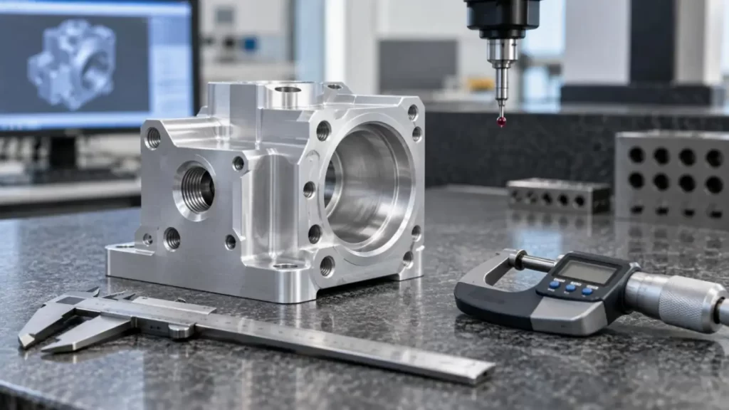
For a precision CNC Aluminum Part, anodizing is not only a surface treatment decision. It is also a dimensional-control decision.
A bore that measures correctly after CNC machining may become undersized after anodizing. A shaft may grow enough to eliminate a sliding clearance. Small threads may tighten, while bearing seats and sealing surfaces may no longer assemble as intended.
At KT, this is why machining tolerance and surface finishing should be reviewed together during DFM rather than treated as two separate production steps.
Why Anodizing Changes CNC Aluminum Part Dimensions
Anodizing converts aluminum at the surface into aluminum oxide. The oxide layer does not simply build outward like paint or powder coating.
Part of the oxide develops into the original aluminum surface, while part grows above it.
For engineering estimates:
• Type II anodizing: commonly approximated as about 2/3 penetration and 1/3 outward growth.
• Type III hard anodizing: often approximated closer to 1/2 penetration and 1/2 outward growth.
These ratios are useful for preliminary tolerance planning, but they are not fixed constants. Actual growth depends on:
• Aluminum alloy
• Coating thickness
• Pretreatment
• Bath chemistry
• Current density
• Temperature
• Sealing process
• Local geometry
For a precision CNC Aluminum Part, the supplier therefore needs both the required coating specification and the final functional dimension.
https://youtube.com/shorts/RWeWAUdh2PQ?feature=share
How Coating Thickness Changes Bores and Shafts
If:
• t = total coating thickness
• f = fraction growing above the original surface
Then approximate outward build-up per surface is:
Build-up = t × f
For a cylindrical feature:
OD change ≈ +2 × t × f
ID change ≈ −2 × t × f
A simplified example shows why this matters:
| Anodizing Process | Nominal Coating | Approx. Outward Growth per Side | Approx. Diameter Effect |
| Type II | 20 μm | ~6.7 μm | ~13.4 μm |
| Type III | 30 μm | ~15 μm | ~30 μm |
| Type III | 50 μm | ~25 μm | ~50 μm |
For a general enclosure, a 0.05 mm dimensional shift may not matter. For a bearing bore, precision locating feature, or close sliding fit, it can cause assembly failure.
That is why a CNC Aluminum Part drawing should clearly state whether critical dimensions apply before or after anodizing.
Type II vs. Type III: Dimensional Control Is Different
Type II and Type III should not be treated as interchangeable finishing options.
| Design Factor | Type II Anodizing | Type III Hard Anodizing |
| Main purpose | Corrosion protection, appearance | Wear resistance, harder surface |
| Typical coating | Thinner | Thicker |
| Dimensional impact | Lower | Higher |
| Precision fit risk | Moderate | High |
| Bearing bores | Evaluate allowance | Often requires compensation or masking |
| Threads | Check fit | More sensitive to coating build-up |
| Typical design priority | Appearance + protection | Wear + service life |
KT supports both Type II and Type III anodizing for applicable aluminum components. The correct choice should be made before final machining dimensions are frozen.
A CNC Aluminum Part originally designed for Type II may require revised allowances if the specification later changes to Type III.
Three Ways to Control Anodizing Allowance
There is no single best strategy for every feature.
1. Machine with a Pre-Anodizing Allowance
This is common for controlled bores, shafts, and slots.
Examples:
• Machine a bore slightly larger before anodizing.
• Machine an external diameter slightly smaller.
• Reserve extra clearance in a sliding interface.
This approach works well when the anodizing process is stable and the required tolerance is realistic.
2. Mask Critical Areas
Masking inhibits oxidation on selected functional surfaces.
It is often considered for:
• Bearing seats
• Precision Dowel holes
• Electrical grounding areas
• Selected threads
• Seals contact surfaces
• Tight fit assembly interfaces
Masking reduces dimensional risk at the expense of increasing the complexity of the process, and requires a clear drawing callout.
3. Finish-Machine After Anodizing
Post-anodizing machining, grinding, honing, or lapping may be used where final dimensional accuracy has priority over retaining the coating.
| Strategy | Dimensional Control | Coating Retained | Relative Cost | Typical Use |
| Pre-machining compensation | Good | Yes | Low–Medium | General precision features |
| Masking | Very good | No coating in masked area | Medium | Bearings, threads, contacts |
| Post-machining | Excellent | Removed locally | Higher | Critical fits and precision bores |
For KT, the decision should be driven by the function of the CNC Aluminum Part, not simply by the easiest finishing route.
Threads Need Separate Consideration
Threaded features are more complicated than a straight bore.
Anodizing grows along:
• Thread crests
• Thread roots
• Thread flanks
This changes effective thread engagement and pitch diameter.
Small threads such as M3, M4, or fine-pitch threads are especially sensitive.
For critical threaded features, designers may need to consider:
• Masking
• Oversize tapping
• Thread chasing after finishing
• Thread inserts
• Increased fit allowance
A simple "subtract twice the coating thickness" rule should not be used blindly for threads.
Alloy and Pretreatment Affect the Final Result
The same anodizing callout does not guarantee identical results on every aluminum alloy.
KT commonly machines alloys such as 6061 and 7075, which differ in strength, alloying content, machinability, corrosion behavior, and anodized appearance.
Pretreatment has its own considerations.
Some processes include:
• Bead blasting
• Chemical etching
• Polishing
• Brushing
and will remove material prior to anodizing.
Therefore, the final dimension of a CNC Aluminum Part is influenced by both material removal before anodizing and oxide growth during anodizing.
This is especially important on:
• Thin-wall parts
• Large flat plates
• Precision housings
• Heat sinks
• Instrument components
• Multi-surface 5-axis parts
KT offers 3-axis and 5-axis CNC machining and can achieve high-precision machining down to approximately ±0.005 mm on suitable parts, depending on geometry, material, feature size, setup, and inspection requirements.
The important point is that machining capability and final finished-part tolerance are not automatically the same number.
Inspect the CNC Aluminum Part Before and After Anodizing
A professional inspection plan should separate machining verification from coating verification.
Before Anodizing
Check:
• Critical CNC dimensions
• Datum relationships
• Bore size
• Thread condition
• Burr removal
• Surface roughness
• Masking locations
After Anodizing
Check:
• Coating thickness
• Final bore and shaft dimensions
• Assembly fit
• Thread engagement
• Masked areas
• Surface appearance
• Critical functional tolerances
A coating can meet the anodizing specification while the finished CNC Aluminum Part still fails dimensional inspection.
Both requirements need independent verification.
Standards to Define Before Production
Depending on the project, drawings or RFQs may reference:
• ISO 7599 for decorative and protective anodizing
• ISO 10074 for hard anodic oxidation
• MIL-PRF-8625 for anodic coatings on aluminum
• ISO 2360 for non-destructive coating thickness measurement
The drawing should also specify the required anodizing type, coating thickness, color, sealing, masking, and whether dimensions apply before or after finishing.
What Buyers Should Include in a CNC Aluminum Part RFQ
To avoid ambiguity, a professional RFQ should define:
• Aluminum alloy and temper
• 2D drawing and 3D model
• Type II or Type III anodizing
• Coating thickness range
• Final critical dimensions
• Tight-tolerance fits
• Bearing seats
• Threads
• Masking areas
• Cosmetic surfaces
• Inspection standard
• Required reports
• Production quantity
For a precision CNC Aluminum Part, dimensional control does not end when CNC machining is complete. The correct approach is to evaluate machining tolerance, anodizing allowance, functional fit, and final inspection as one process chain.
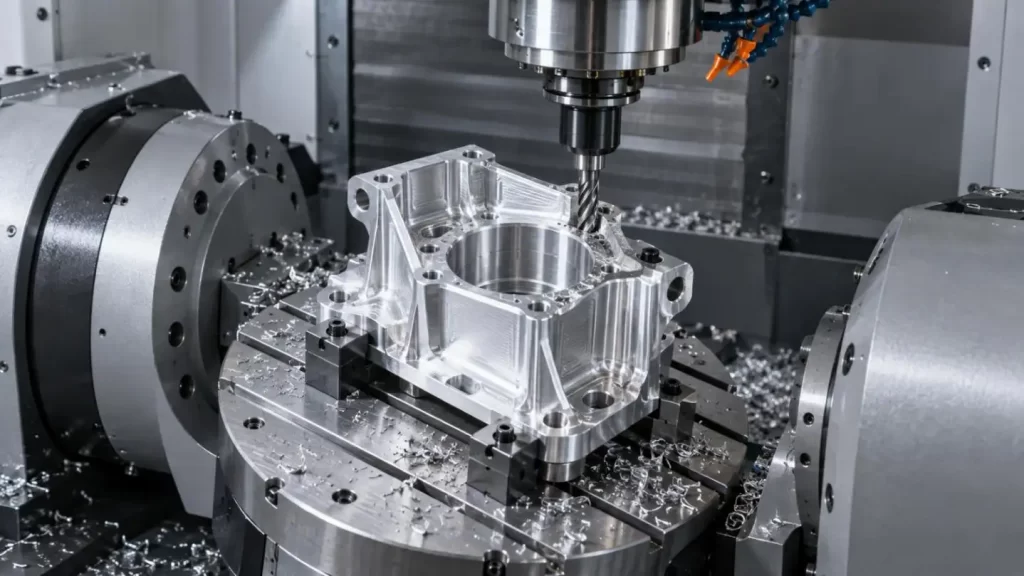
KT combines CNC, aluminum, DFM, and surface-finishing services. If your CNC Aluminum Part has tight bores, threads, bearing fits, or hard-anodized surfaces, you can send the drawing to KT to analyze the machining allowance and required finish for that part before production.
FAQs
Q1. Can KT manufacture tight-tolerance CNC Aluminum Part components?
Yes. KT provides precision CNC machining for aluminum components, with high-precision tolerances down to approximately ±0.005 mm for suitable geometries, materials, and process conditions.
Q2. Does KT support anodizing for CNC Aluminum Part projects?
Yes. KT supports surface finishing options for aluminum parts, including Type II and Type III anodizing for applications requiring corrosion protection, appearance, or wear resistance.
Q3. Can KT compensate for anodizing thickness during CNC machining?
Yes. For critical dimensions, KT can review coating thickness, functional fits, and drawing requirements to determine whether pre-machining allowance, masking, or post-machining is more appropriate.
Q4. Can KT machine both 6061 and 7075 aluminum?
Yes. KT works with commonly used CNC aluminum alloys including 6061 and 7075, with material selection based on strength, machinability, corrosion performance, and finishing requirements.
Q5. Does KT offer 5-axis machining for complex CNC Aluminum Part designs?
Yes. KT provides both 3-axis and 5-axis CNC machining, allowing complex multi-surface aluminum components to be produced with fewer setups and reduced datum-transfer error.
Talk to the Manufacturer, Not a Middleman
Resources & Insights
-
 Industry Insights
CNC Machining Robotic Parts: How GD&T Controls Robot Assembly Accuracy
2026-09-24By KT Engineering -
 Industry Insights
Hardware Stamping Springback Control for High-Strength Steel Parts
2026-09-24By KT Engineering -
 Industry Insights
Spring Stamping Fatigue Life: How Geometry, Material and Edge Quality Affect Cycle Life
2026-09-24By KT Engineering -
 Industry Insights
Mechanical Automation Parts for Robot End Effectors and Positioning Accuracy
2026-09-23By KT Engineering