Contact Us
 Home /
Spring Stamping Fatigue Life: How Geometry, Material and Edge Quality Affect Cycle Life


Table of Contents
- Why Spring Stamping Parts Fail Even When Dimensions Are Correct
- Geometry Controls Where Fatigue Damage Starts
- Material Selection Must Include Temper and Function
- Edge Quality Can Become the Dominant Fatigue Variable
- Spring Stamping Must Be Matched to the Actual Assembly
- Tooling Stability Matters in High-Volume Spring Stamping
- Material Fatigue Data Is Not Finished-Part Validation
- What Buyers Should Include in a Spring Stamping RFQ

For a Spring Stamping component, passing dimensional inspection does not automatically mean it will survive the required number of cycles. Clips, electrical contacts, retaining springs, battery terminals and formed spring arms often fail because fatigue is governed by local cyclic strain, not simply by nominal dimensions or material tensile strength.
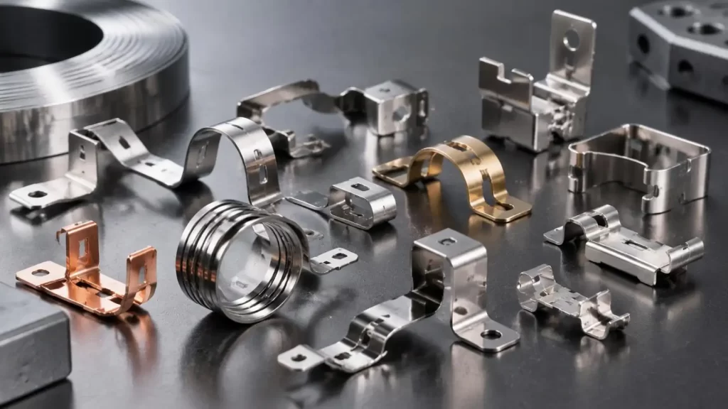
From KT's manufacturing perspective, reliable Spring Stamping requires five variables to be considered together:
•Spring geometry and local stress concentration;
•Material grade, temper and rolling direction;
•Punched-edge and burr condition;
•Actual preload and working travel;
•Tooling stability during volume production.
The engineering question is therefore not only "Is the part within tolerance?" but "Will the same geometry, force and edge condition remain stable after hundreds of thousands of cycles?"
Why Spring Stamping Parts Fail Even When Dimensions Are Correct
Fatigue normally begins at a localized weak point rather than across the entire spring.
Common crack-initiation areas include:
•The root of a tight bend;
•Narrow spring arms;
•Slots or pierced holes near a stressed section;
•Blanked edges carrying tensile stress;
•Abrupt width transitions;
•Regions exposed to assembly overtravel.
During repeated deflection, microscopic damage accumulates. A Spring Stamping part may remain below its static failure load while still developing a fatigue crack over time.
Two loading variables should be defined early:
Stress amplitude describes how much stress changes during each cycle, while mean stress is influenced by preload and installed position. Increasing preload without changing the visible operating stroke can still move the spring into a less favorable fatigue condition.
Geometry Controls Where Fatigue Damage Starts
In Spring Stamping design, bend radius, thickness and effective spring length cannot be evaluated independently.
A useful design parameter is the bend radius-to-thickness ratio, r/t. When the inside radius becomes very small relative to material thickness, deformation concentrates in the bend root. This can increase local strain and reduce fatigue margin.
| Geometry Variable | Change | Likely Fatigue Effect | Design Trade-Off |
| Bend radius | Smaller | Higher local strain | More compact geometry |
| Material thickness | Higher | Higher stiffness | Greater force, less flexibility |
| Spring arm length | Longer | Lower strain at same travel | Larger envelope |
| Slot/notch radius | Smaller | Higher stress concentration | Compact feature design |
| Width transition | Abrupt | Localized peak stress | Simpler stamping layout |
A frequent mistake is increasing thickness to "make the spring stronger." For a fixed working displacement, additional thickness can significantly increase stiffness and bending stress. A better solution may be a longer spring arm, smoother transition, larger local radius or revised load path.
Material Selection Must Include Temper and Function
The best Spring Stamping material depends on whether the component primarily carries mechanical load, resists corrosion or conducts current.
| Material | Main Strength | Main Limitation | Common Spring Stamping Use |
| High-carbon spring steel | High elastic strength | Corrosion protection may be needed | Clips, retainers, mechanical springs |
| 301 stainless steel | Strength plus corrosion resistance | Temper strongly affects formability | Automotive and industrial springs |
| Phosphor bronze | Conductivity and corrosion resistance | Generally lower strength than spring steel | Contacts and electrical terminals |
Material grade alone is insufficient. Engineers should also control:
•Temper or cold-work condition;
•Hardness range;
•Sheet thickness;
•Rolling direction;
•Surface condition;
•Plating or corrosion protection.
A high-strength material can support greater spring force, but it may also have less forming margin around small radii or pierced features. In Spring Stamping, stronger material is not automatically more fatigue-resistant.
Edge Quality Can Become the Dominant Fatigue Variable
Stamped edges deserve particular attention in fatigue-critical parts.
A conventional blanked edge may contain:
•Rollover;
•Burnished zone;
•Fracture zone;
•Burr.
If the edge lies in a high-tensile-stress region, a burr or fracture irregularity can act as a local notch. This leads to a practical manufacturing chain:
Die wear → Clearance variation → Edge degradation → Higher local stress concentration → Earlier crack initiation
This is why Spring Stamping fatigue life can change during a long production run even when major dimensions remain within tolerance.
For fatigue-sensitive edges, possible control strategies include:
Optimized Punch-to-Die Clearance
Correct clearance helps stabilize the burnished and fracture zones and reduces uncontrolled edge damage.
Controlled Burr Direction
Where geometry allows, the burr side should be considered relative to the highest tensile-stress surface.
Local Deburring or Edge Finishing
Secondary finishing can be applied selectively to critical edges rather than to the entire part.
Shaving or Secondary Sizing
For highly fatigue-sensitive features, additional edge-control operations may provide more consistent geometry, although with higher tooling and process cost.
Spring Stamping Must Be Matched to the Actual Assembly
A cycle-life target such as "500,000 cycles" has little engineering value without test conditions.
A useful Spring Stamping specification should define:
•Preload or installed position;
•Minimum and maximum travel;
•Force at defined displacement;
•Operating frequency;
•Temperature range;
•Vibration exposure;
•Corrosion or moisture environment;
•Allowable overtravel;
•Failure criterion.
For example, a prototype tested at 1.5 mm travel may pass comfortably, while the assembled mechanism may force the same part to 1.8 or 2.0 mm because of stack-up variation.
That additional travel can materially change local strain.
Tooling Stability Matters in High-Volume Spring Stamping
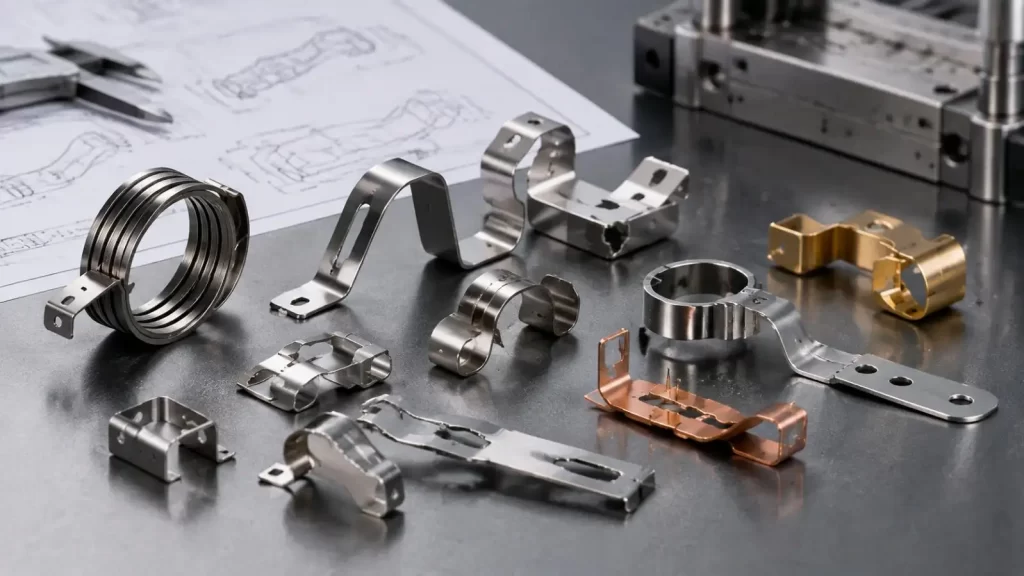
At KT, the manufacturing discussion should continue beyond prototype approval. For Spring Stamping produced with progressive or compound tooling, long-run consistency depends on the condition of punches, dies, pilots, forming inserts and feed control.
Important production characteristics include:
•Burr growth;
•Free height or free angle;
•Spring force;
•Critical bend radii;
•Pierced-feature location;
•Material-lot consistency;
•Tool wear trend.
KT's precision stamping capabilities include progressive and compound die production, with stamping tolerances selected according to material, geometry, thickness and forming sequence. For fatigue-critical parts, the practical objective is not simply achieving a tight number on the drawing, but maintaining the same functional spring behavior across production lots.
Material Fatigue Data Is Not Finished-Part Validation
Material S-N curves are valuable for screening designs, but they do not include every feature created during Spring Stamping.
Finished parts introduce additional variables such as:
•Forming strain;
•Punched edges;
•Residual stress;
•Bend geometry;
•Plating;
•Assembly preload.
A more reliable validation sequence is:
Material data → Prototype component test → Production-representative test → Lot/process monitoring
The component cycle test should reproduce the real spring stroke, preload and environmental conditions. For critical programs, multiple samples should be tested because fatigue life naturally shows statistical scatter.
What Buyers Should Include in a Spring Stamping RFQ
For fatigue-sensitive applications, a drawing should be accompanied by functional requirements.
| RFQ Item | Why It Matters |
| Material and temper | Controls elastic and forming behavior |
| Thickness | Influences stiffness and stress |
| Working travel | Defines cyclic deformation |
| Preload | Changes mean stress |
| Force requirement | Defines spring function |
| Cycle-life target | Establishes validation objective |
| Burr/edge requirement | Controls crack-sensitive features |
| Environment | Affects corrosion and relaxation |
| Inspection plan | Supports repeatable production |
The most reliable Spring Stamping design is rarely the one with the strongest material or the tightest tolerance alone. Fatigue life depends on how geometry, material condition, edge quality, real working travel and tooling stability interact.
KT provides DFM review, evaluation of materials/tolerances, tooling development, prototyping, and validation as well as transitioning to volume stamping for new Spring Stamping projects. Evaluating fatigue critical bends, edges, and load conditions early in the design process may help avoid potential redesigns prior to the completion of the progressive die.
FAQs
Q1. What Spring Stamping services does KT provide?
KT supports precision metal stamping for spring clips, contacts, terminals, brackets and other formed components. Its capabilities include progressive die and compound die manufacturing for prototype development and volume production.
Q2. Can KT manufacture fatigue-critical Spring Stamping parts?
Yes. KT can review fatigue-sensitive features such as bend radii, spring arms, slots, pierced edges and high-stress transitions during DFM. Final cycle-life requirements should be defined through application-specific testing.
Q3. What materials can KT use for Spring Stamping?
KT works with commonly stamped materials including stainless steel, carbon steel, aluminum, brass and other engineering metals. Material grade, temper and thickness should be selected according to spring force, corrosion resistance and fatigue requirements.
Q4. Can KT help optimize Spring Stamping bend geometry?
Yes. During DFM review, KT can evaluate bend radius, material thickness, forming sequence and feature location to identify areas that may create excessive deformation or manufacturing instability.
Q5. How does KT control burrs on Spring Stamping parts?
Burr condition is influenced by punch-to-die clearance, tooling condition, material thickness and die wear. KT can consider these factors during tooling development and recommend secondary finishing where fatigue-critical edges require additional control.
Talk to the Manufacturer, Not a Middleman
Resources & Insights
-
 Industry Insights
CNC Machining Robotic Parts: How GD&T Controls Robot Assembly Accuracy
2026-09-24By KT Engineering -
 Industry Insights
Hardware Stamping Springback Control for High-Strength Steel Parts
2026-09-24By KT Engineering -
 Industry Insights
Spring Stamping Fatigue Life: How Geometry, Material and Edge Quality Affect Cycle Life
2026-09-24By KT Engineering -
 Industry Insights
Mechanical Automation Parts for Robot End Effectors and Positioning Accuracy
2026-09-23By KT Engineering