Contact Us
 Home /
Die Mold Parts Material Selection: H13 vs D2 vs Carbide for Different Tooling Applications


Table of Contents
- Start With the Failure Mode of Die Mold Parts
- H13 Die Mold Parts: Managing Heat and Mechanical Stress
- D2 Die Mold Parts: Prioritizing Abrasive Wear Resistance
- Carbide Die Mold Parts: Wear Resistance Requires Grade Selection
- Geometry Can Override the Material Ranking
- Material Selection Must Match the Manufacturing Route
- KT Precision Capability for Die Mold Parts
- Selecting Die Mold Parts by Tool-Life Economics

At KT, we do not select material for Die Mold Parts by hardness alone. A punch that fails from abrasive wear requires a different material strategy from a core pin that fractures under bending or an insert exposed to repeated thermal cycling.
For practical tooling design, we use a broader decision chain:
Operating condition → Failure mode → Material properties → Part geometry → Heat treatment → Machining route → Inspection → Tool-life economics
This is why H13, D2, and carbide should be treated as different engineering solutions rather than ranked simply from "good" to "best."
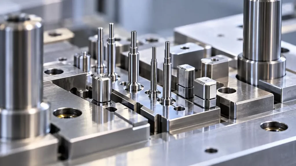
Start With the Failure Mode of Die Mold Parts
Before selecting material, identify what limits the current tool life.
Classical failure modes are:
•Abrasive wear: Continuous loss of edge and roundness of punch and forming tools.
•Plastic deformation: Local change of tool geometry due to high compression.
•Chipping: Brittle fracture at sharp edges.
•Cracking: Failure due to impact, bending, etc. with insufficient support.
•Thermal fatigue: Repeated heating and cooling causing heat checking or cracking.
•Dimensional instability: Change of critical dimensions due to heat treatment or loss of residual stresses.
The main challenge for the designer is the balancing act between different properties of a material. For example the balance between hardness and wear resistance on one hand, and fracture toughness on the other. Hardness and wear resistance of a material can be improved by processing. However toughness or ductility can be reduced by processing and thus impact can be more critical than wear.
H13 Die Mold Parts: Managing Heat and Mechanical Stress
H13 is a hot-work tool steel developed for applications involving combined thermal and mechanical loading. Published H13 data emphasize thermal-shock resistance, thermal-fatigue resistance, high-temperature strength, toughness, and dimensional stability during hardening.
For Die Mold Parts, H13 is commonly considered for:
•Die-casting inserts;
•Hot cores;
•Thermally loaded mold inserts;
•Tooling exposed to repeated heating and cooling.
The important point is that H13 is not selected because it provides the maximum possible wear resistance. It is selected where heat checking, cracking, and thermal cycling may determine tool life.
A harder but less damage-tolerant material can perform worse if thermal stress becomes the dominant failure mechanism.
D2 Die Mold Parts: Prioritizing Abrasive Wear Resistance
D2 is more closely associated with cold-work tooling. Its strengths include high abrasive-wear resistance, compressive strength, through-hardening capability, and dimensional stability during hardening. It is commonly applied to blanking, forming, punches, plates, and wear components.
D2 Die Mold Parts are therefore suitable candidates when the dominant problem is:
•Sliding or abrasive contact;
•Repetitive compressive loading;
•Cutting-edge degradation;
•Dimensional loss caused by wear.
However, D2 should not automatically be specified for every punch. Comparative tool-steel data show that reference D2 provides strong abrasive-wear resistance but substantially lower edge-chipping and gross-cracking resistance than tougher cold-work grades.
For thin punches, sharp transitions, unsupported features, or impact-loaded components, we therefore evaluate fracture risk before increasing hardness.
Carbide Die Mold Parts: Wear Resistance Requires Grade Selection
"Carbide" is not a single material specification.
Cemented carbide combines a hard carbide phase—typically tungsten carbide—with a metallic binder. Grain size and binder content change the balance between wear resistance and toughness. Finer-grain, lower-binder grades generally favor hardness and wear resistance, while higher binder content and coarser structures can provide greater toughness.
Carbide Die Mold Parts are worth evaluating for:
•High-cycle precision punches;
•Wear inserts;
•Small precision pins;
•Components where dimensional wear limits production consistency.
But carbide also requires careful consideration of impact, edge loading, support, section thickness, grinding requirements, and manufacturing cost.
H13 vs D2 vs Carbide
| Engineering Factor | H13 | D2 | Carbide |
| Primary strength | Thermal fatigue + toughness | Abrasive wear + compression | Very high wear resistance |
| Typical environment | Hot work | Cold work | Severe repetitive wear |
| Impact tolerance | Relatively favorable | More limited | Grade-dependent |
| Thermal cycling | Strong candidate | Usually secondary | Application-dependent |
| Edge-chipping risk | Moderate | Must be evaluated | Critical for some grades |
| Typical parts | Hot inserts, cores | Punches, dies, wear inserts | Precision punches, pins, inserts |
| Manufacturing difficulty | Moderate | Higher after hardening | Specialized |
Geometry Can Override the Material Ranking
At KT, we evaluate Die Mold Parts as structural components, not just material samples.
Long Core Pins
A high length-to-diameter ratio increases deflection. Repeated lateral loading can create bending fatigue, so maximum hardness may be less valuable than fracture resistance.
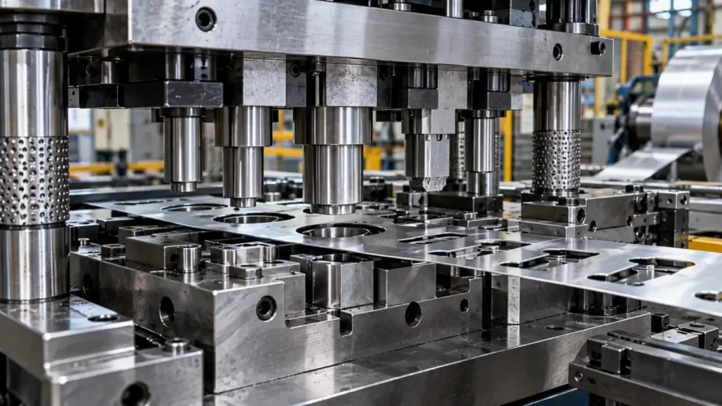
Sharp Punch Profiles
A sharp corner concentrates stress. D2 or carbide may resist wear well, but insufficient edge toughness can produce micro-chipping.
Large Inserts
Large cross-sections require attention to:
•Heat-treatment uniformity;
•Residual stress;
•Dimensional movement;
•Grinding allowance after hardening.
Micro Features
Small Die Mold Parts require control of edge radius, grinding forces, EDM condition, surface integrity, and—in carbide components—grade and grain structure.
Material Selection Must Match the Manufacturing Route
The selected material determines how final accuracy is produced.
A typical precision route may include:
CNC roughing → Heat treatment → EDM / Wire EDM → Precision grinding → Polishing → Dimensional inspection
Critical dimensions are often left with finishing allowance before heat treatment because hardening can introduce distortion or residual-stress movement.
KT combines CNC machining with Wire EDM, Sinker EDM, grinding, and polishing for custom mould components, allowing the process sequence to be selected according to geometry, material, datum structure, and functional surfaces.
KT Precision Capability for Die Mold Parts
Tolerance should be assigned according to function rather than applying the smallest value across an entire drawing.
KT's manufacturing capability:
| Process | Typical Capability | High-Precision Capability |
| CNC Machining | ±0.05 mm | ±0.005 mm |
| Tool & Die | ±0.02 mm | ±0.005 mm |
| 5-Axis / Complex Components | ±0.03 mm | ±0.002 mm |
Actual achievable tolerance depends on material, geometry, feature size, fixturing, machining strategy, and inspection conditions. KT therefore reviews critical datums, fits, profiles, flatness, concentricity, and runout rather than assuming every feature needs the same tolerance. CMM inspection is used for dimensional verification where required.
Selecting Die Mold Parts by Tool-Life Economics
The final choice should not be based only on material price.
A useful comparison is:
Part Cost ÷ Verified Production Life
Carbide may justify its higher manufacturing cost when repetitive wear drives frequent replacement. D2 can be more economical where abrasive wear dominates but extreme carbide wear resistance is unnecessary. H13 can be the better decision when thermal fatigue or cracking would end tool life before abrasive wear becomes critical.
At KT, we therefore review Die Mold Parts from the complete tooling requirement: component geometry, material, expected failure mode, tolerance, heat treatment, surface condition, production volume, and required tool life.
For custom Die Mold Parts, customers can submit 2D drawings or 3D CAD files so that material selection, tolerance strategy, CNC/EDM/grinding sequence, and inspection requirements can be evaluated together. Learn more about KT's precision machining and tooling capabilities at KT.
FAQs
Q1. What types of Die Mold Parts can KT manufacture?
KT manufactures custom punches, inserts, core pins, dies, mold components and other precision tooling parts from customer drawings or CAD files.
Q2. What materials does KT use for Die Mold Parts?
KT works with tool steels, hardened steels, stainless steels and carbide. Material selection depends on wear, load, temperature, geometry and tool-life requirements.
Q3. Can KT manufacture H13 Die Mold Parts?
Yes. H13 can be considered for Die Mold Parts exposed to thermal cycling, hot-work conditions and applications requiring a balance of toughness and heat resistance.
Q4. Can KT produce D2 Die Mold Parts?
Yes. D2 is commonly considered for punches, dies and wear components where abrasive wear and compressive loading are major design factors.
Q5. Does KT manufacture carbide Die Mold Parts?
Yes. KT can manufacture carbide tooling components where high wear resistance and dimensional stability justify the material and processing requirements.
Talk to the Manufacturer, Not a Middleman
Resources & Insights
-
 Industry Insights
Custom Aluminum Automation Parts Machining for Robotic Joint Housings
2026-10-21By KT Engineering -
 Industry Insights
Automotive Stamping Die Design: How Tooling Accuracy Affects Final Part Tolerance
2026-10-21By KT Engineering -
 Industry Insights
GD&T for Industrial Equipment Parts: Controlling Position, Flatness and Concentricity
2026-10-21By KT Engineering -
 Industry Insights
Inconel Aerospace Components: Managing Heat, Tool Wear and Machining Stability
2026-10-21By KT Engineering