Contact Us
  Home /
 4 Axis Machining for Complex Parts: What Geometries Can Be Machined in One Setup?


Table of Contents
- When Multiple Faces Become a Setup Problem
- How the Fourth Axis Changes Tool Access
- Which Geometries Are Good Candidates for 4 Axis Machining?
- 3 Axis vs. Indexed 4 Axis vs. Simultaneous 4 Axis vs. 5 Axis
- One Setup Does Not Automatically Mean Higher Accuracy
- Before Selecting 4 Axis Machining, Check the Complete Rotary Envelope
- Setup and Calibration Affect Long-Term Repeatability
- How Should 4-Axis Parts Be Verified?
-
What Should You Send for a 4 Axis Machining Quote?
- Is Your Complex Part Really a 4-Axis Part?
-
FAQs
- Q1. Does KT TOOL offer 4 Axis Machining for complex CNC components?
- Q2. What kinds of components can KT TOOL create with 4 Axis Machining?
- Q3. Is KT TOOL able to machine multiple sides of a component with just a single setup?
- Q4. What is the general CNC milling tolerance for KT TOOL?
- Q5. Can KT TOOL be used for both 4-axis and 5-axis machining?

Complex CNC parts are not difficult simply because they contain many features. The real manufacturing challenge often appears when critical holes, pockets, ports, and profiles are distributed around several faces and must maintain a precise relationship to the same datum.
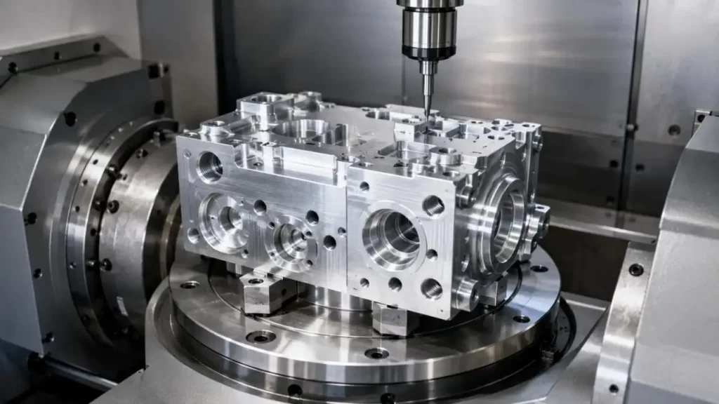
This is where 4 Axis Machining can be valuable. By adding a controlled rotary axis to conventional X, Y, and Z motion, the process can expose several sides of a workpiece without repeatedly removing and re-clamping it. However, not every complex part is a suitable 4-axis part.
The key question is: Can the critical geometry be reached by rotating the workpiece around one controlled axis while maintaining practical tool and fixture clearance?
When Multiple Faces Become a Setup Problem
Consider a housing with a central bore, side ports, threaded holes at 90° intervals, and mounting features on several faces. A 3-axis machine may produce every individual feature, but several setups may be required.
Each re-clamping operation can introduce another source of:
•Datum transfer error;
•Fixture positioning error;
•Angular misalignment;
•Inspection complexity;
•Operator handling time.
For features with tight positional relationships, reducing these datum transfers may matter more than simply increasing cutting speed.
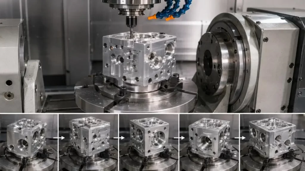
With 4 Axis Machining, the workpiece can remain referenced to the same fixture while the rotary axis indexes it to different orientations.
How the Fourth Axis Changes Tool Access
A typical 4-axis CNC configuration combines X, Y, and Z linear movement with an A, B, or C rotary axis. In many milling applications, the additional axis rotates the workpiece while the cutting tool maintains a relatively consistent orientation.
There are two important machining modes.
Indexed 4 Axis Machining
In indexed, or 3+1 machining, the rotary axis moves to a defined angle and stops before cutting begins.
For example:
0° → machining → 90° → machining → 180° → machining
This approach works well for:
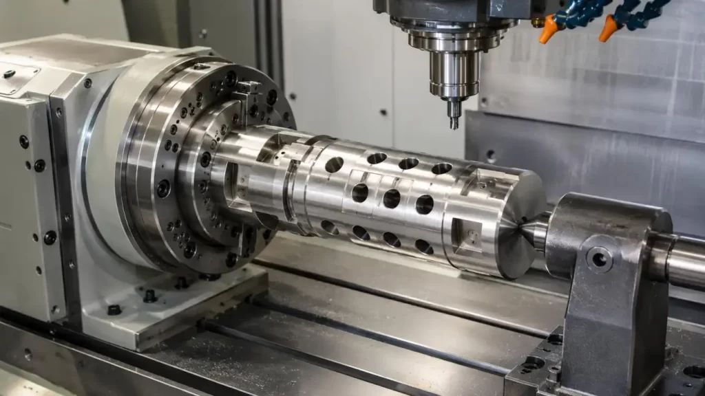
•Radial holes;
•Threaded ports;
•Flats;
•Bolt patterns;
•Multi-face pockets;
•Features positioned around cylindrical parts.
Simultaneous 4 Axis Machining
In simultaneous 4 Axis Machining, the rotary axis moves while one or more linear axes are cutting.
This is more appropriate for:
•Helical grooves;
•Wrapped profiles;
•Continuous rotary contours;
•Cam-like surfaces;
•Complex features around cylindrical bodies.
A machine equipped with a fourth axis should therefore not automatically be assumed to support every simultaneous four-axis toolpath. Machine configuration, controller capability, CAM programming, and collision control must also be considered.
Which Geometries Are Good Candidates for 4 Axis Machining?
The best candidates generally share one characteristic: their critical features can be exposed through rotation around a common axis.
| Part Geometry | 4-Axis Suitability | Typical Strategy |
| Radial holes around a shaft | Excellent | Indexed |
| Multi-angle flats | Excellent | Indexed |
| Side ports on housings | Excellent | Indexed |
| Circumferential slots | Good | Indexed / simultaneous |
| Helical grooves | Good | Simultaneous |
| Wrapped engraving or profiles | Good | Simultaneous |
| Deep pockets | Conditional | Tool access dependent |
| Compound-angle holes | Limited | Often 5-axis |
| Deep undercuts | Poor | Additional tool orientation needed |
| Freeform surfaces requiring changing tool tilt | Poor | Usually 5-axis |
This distinction is important. A visually complicated part may still be ideal for 4 Axis Machining if its features are organized around one rotational centerline. A smaller part with compound-angle holes may require 5-axis machining instead.
3 Axis vs. Indexed 4 Axis vs. Simultaneous 4 Axis vs. 5 Axis
Selecting the process should be based on geometry rather than simply choosing the machine with the highest axis count.
| Process | Best Application | Main Limitation |
| 3-axis | Features accessible from one direction | Multiple setups for side features |
| Indexed 4-axis | Multi-face and radial geometry | Rotary axis stops during cutting |
| Simultaneous 4-axis | Helical and wrapped geometry | Higher CAM complexity |
| 5-axis | Compound angles and changing tool orientation | Higher programming and machine cost |
For example, a valve body with ports every 90° may gain little from full 5-axis machining if indexed 4 Axis Machining can expose every critical feature in one fixture.
KT TOOL uses 3-axis, 4-axis, and 5-axis CNC equipment, including DMG MORI, Mazak, and Haas machines, allowing the machining route to be selected according to actual geometry instead of applying one process to every complex part. Its CNC resources include more than 70 milling, turning, and mill-turn centers.
One Setup Does Not Automatically Mean Higher Accuracy
Reducing setups can improve datum consistency, but 4 Axis Machining accuracy still depends on the complete machining system.
Important variables include:
•Rotary-axis positioning accuracy;
•Rotary repeatability;
•Centerline calibration;
•Chuck and fixture runout;
•Clamping rigidity;
•Tool length and deflection;
•Cutting force;
•Thermal stability.
Rotary error also becomes more significant as part radius increases. A small angular positioning deviation creates a larger linear displacement at a feature located farther from the rotary centerline.
This is why machine-axis specifications should never be treated as identical to finished-part tolerance.
KT TOOL's CNC milling services offer tolerances of ±0.01 mm and provide surface finishes of Ra 0.8–1.6 μm. For specific features, we are able to provide tolerances of ±0.001 mm. A number of factors impact what tolerances we are able to offer, such as part geometry, material, size of the feature, machining method, and how the part is going to be measured.
Before Selecting 4 Axis Machining, Check the Complete Rotary Envelope
From the CAD model, it may appear to be fully rotatable and translatable, but there are constraints with machining.
Engineers need to verify:
•Maximum workpiece swing;
•Chuck diameter;
•Fixture height;
•Spindle and holder clearance;
•Tool reach;
•Tailstock position;
•X/Y/Z travel after rotation.
Long shafts may require a tailstock to control vibration and bending. Deep features may require longer cutters, but increasing tool overhang also increases deflection.
Therefore, the correct question is not simply "Can the fourth axis rotate the part?" It is:
Can the part rotate through every required position while the cutter, holder, fixture, and machine structure remain clear?
Setup and Calibration Affect Long-Term Repeatability
For production 4 Axis Machining, setup verification should include the rotary centerline, work offset, chuck or fixture runout, and probing system.
For long components, tailstock alignment also matters. Excessive support force can distort a slender workpiece, while insufficient support can allow chatter.
Periodic verification becomes especially important when a drawing controls relationships such as:
•Hole position;
•Runout;
•Perpendicularity;
•Angular orientation;
•Concentric relationships.
How Should 4-Axis Parts Be Verified?
Machine accuracy and part inspection are two different tasks.
Machine-tool positioning and rotary-axis behavior may be evaluated using relevant standards such as ISO 230 and ISO 10791 series methods. Finished parts, however, must be inspected against the actual drawing and its dimensional or GD&T requirements.
Depending on the component, verification may include:
•CMM inspection;
•Bore and diameter measurement;
•Positional measurement;
•Runout inspection;
•In-process probing;
•Material certification.
KT TOOL operates an ISO 9001:2015 quality management system and lists CMM inspection and material certificates as part of its traceability approach.
What Should You Send for a 4 Axis Machining Quote?
Before selecting a machining route, a supplier should review more than a 3D model.
A useful RFQ should include:
•STEP, STP, IGES, or another CAD file
•2D drawing
•Material specification
•Critical tolerances and GD&T
•Surface finish
•Heat treatment or coating
•Prototype or production quantity
•Inspection requirements
KT TOOL also provides engineering review and DFM support before production. This allows engineers to determine whether a component is better suited to 3-axis machining, indexed 4 Axis Machining, simultaneous multi-axis machining, or a 5-axis process before unnecessary fixture or machining cost is introduced.
Is Your Complex Part Really a 4-Axis Part?
A strong candidate for 4 Axis Machining normally has critical features distributed around one common rotational axis, requires limited changes in tool orientation, and provides enough clearance for the fixture and cutting system.
If the design instead requires compound-angle machining, a second independent rotational direction, or continuous changes in tool tilt, 5-axis machining may be more practical.
More axes do not equate to greater efficiency. The intent is to implement the least complex machining strategy that can consistently produce and verify the required geometry.
For business involving complex housings, shafts, connectors, valve components, brackets, and similar precision components, KT TOOL can optimize the CAD model, and evaluate the drawing, datum structure, tolerancing, and quantity to assist in the selection of an appropriate 3 axis, 4 axis, or 5 axis machining process. Early submission of the complete drawing package enables the identification of tool access, workholding, and inspection challenges prior to the commencement of production.
FAQs
Q1. Does KT TOOL offer 4 Axis Machining for complex CNC components?
Yes. Within KT TOOL's CNC machining capabilities, 3-axis, 4-axis, and 5-axis CNC machining is available. DMG MORI, Mazak, and Haas are some of the machines used. The machining approach is determined based on part geometry, required tolerances, datums, and accessibility of the tools.
Q2. What kinds of components can KT TOOL create with 4 Axis Machining?
4 Axis Machining is great for components with features that are arrayed around a singular axis of rotation. Some examples of components suitable for 4 Axis Machining are housings, shafts, connectors, valve parts, brackets, parts with radial holes, and parts that have features on multiple faces. Some of these precision CNC components are part of KT TOOL's machining applications.
Q3. Is KT TOOL able to machine multiple sides of a component with just a single setup?
If the part is designed and a suitable workholding is provided, it is possible to use 4 Axis Machining to access multiple sides of a workpiece without the need for repeated manual setups. This method helps improve the precision of the machining in regards to the relationship of multiple features.
Q4. What is the general CNC milling tolerance for KT TOOL?
For CNC milling, KT TOOL claims a machining tolerance of ±0.01 mm and a typical surface finish of Ra 0.8–1.6 μm. For specific features, tolerances may be determined based on a number of different factors which may include the part geometry and features, the selected machining process, the part material, and the required inspection.
Q5. Can KT TOOL be used for both 4-axis and 5-axis machining?
Certainly. KT TOOL supports 3-axis and 4-axis, as well as 5-axis CNC machining. This offers engineers the option of using 4-axis machining for parts that require one degree of rotational freedom, and using 5-axis machining for compound angles, complex multi-surface geometries, and for varying the tool orientation.
Talk to the Manufacturer, Not a Middleman
Resources & Insights
-
 Industry Insights
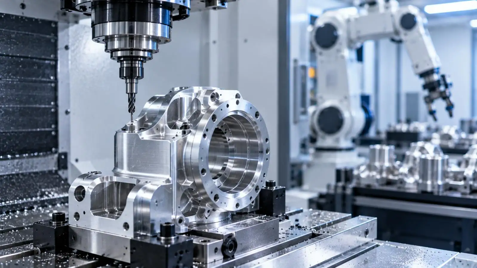
CNC Machining Robotic Parts: How GD&T Controls Robot Assembly Accuracy
2026-09-24By KT Engineering -
 Industry Insights
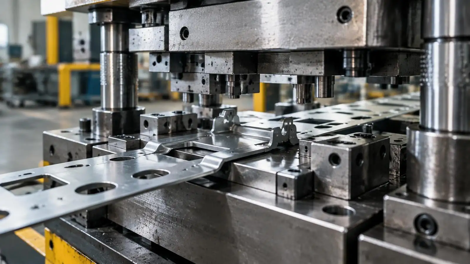
Hardware Stamping Springback Control for High-Strength Steel Parts
2026-09-24By KT Engineering -
 Industry Insights
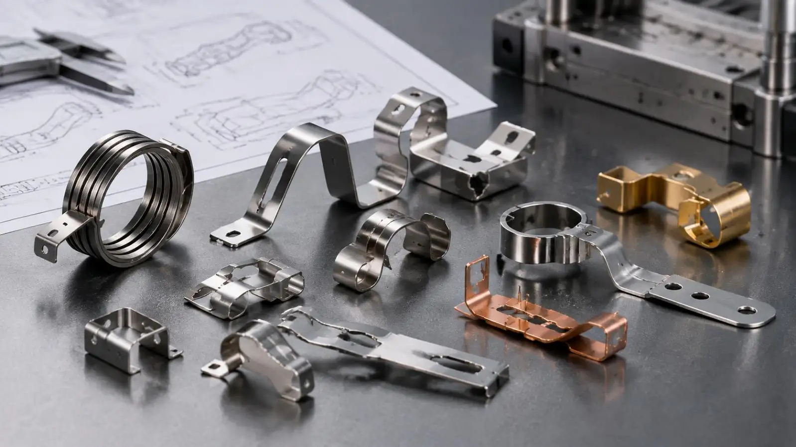
Spring Stamping Fatigue Life: How Geometry, Material and Edge Quality Affect Cycle Life
2026-09-24By KT Engineering -
 Industry Insights
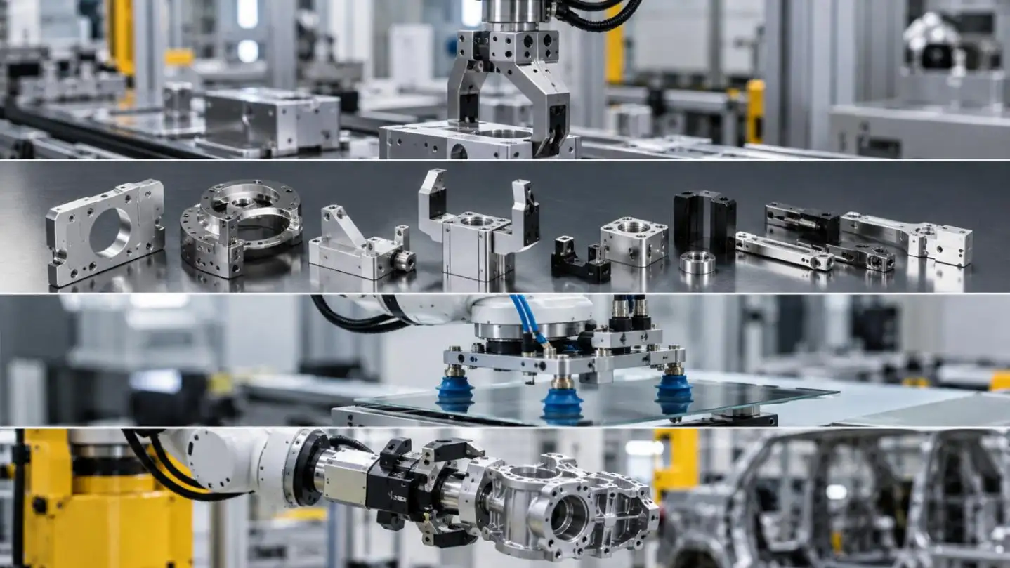
Mechanical Automation Parts for Robot End Effectors and Positioning Accuracy
2026-09-23By KT Engineering