Contact Us
  Home /
 Connector Mold Components for Automotive High-Voltage Connectors


Table of Contents
- Why High-Voltage Connector Failures Often Begin with Small Mold Features
- How Electrical Requirements Become Mold Geometry
- Which Connector Mold Components Need the Tightest Control?
- Steel, Carbide or Replaceable Inserts?
- Resin Selection Changes the Tooling Strategy
- Match the Mold to the Complete High-Voltage Connector System
- Design Connector Mold Components for Maintenance, Not Only First-Off Samples
- Validate the Connector, Not Just the Mold

Automotive high-voltage connectors are no longer defined only by terminal size or current capacity. In EV battery systems, PDU units, inverters, motors, OBCs and DC/DC converters, the connector housing must maintain electrical insulation, terminal position, sealing geometry and mechanical stability under heat, vibration and long production runs.
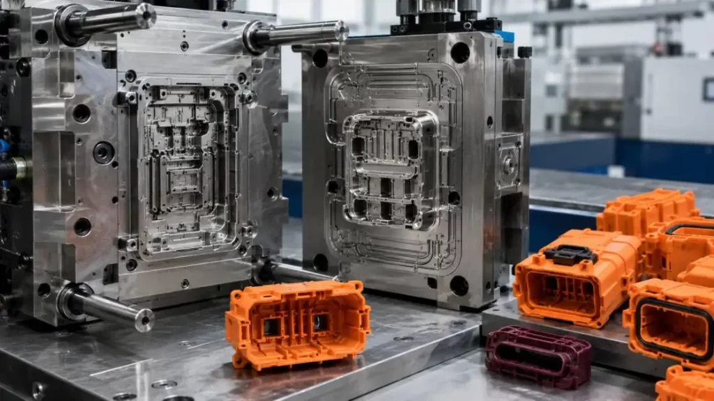
These requirements place unusual demands on Connector Mold Components. A small core pin, cavity insert or shut-off surface can influence terminal alignment, creepage distance, flash formation and seal compression. Therefore, designing Connector Mold Components for high-voltage applications requires more than simply tightening every dimensional tolerance.
Why High-Voltage Connector Failures Often Begin with Small Mold Features
Failures related to connectors can be attributed to common issues with mold geometry.
•Movement of terminals: If terminal locating features are poorly designed, the terminals can be displaced by the injection pressure moving the terminals from their pre-positioned location.
•Flashing: If there is excessive clearance or wear on an insert, there can be a resin flash at the electrical interface.
•Warping: Due to glass-fiber orientation, uneven cooling can result in variation to terminal spacing, flatness of the flanges, and the compression of the seals.
•Chipping of insulation cores: Due to their long and thin design, creepage chip cores are easy to deflect and chip.
•Inconsistent production: A mold can produce samples of a wider dimension, even though early samples may be acceptable, because of worn inserts and shut offs.
For this reason, the Connector Mold Components that are critical should be assigned a classification of their function, rather than the similar tolerance being applied to the entire mold.
How Electrical Requirements Become Mold Geometry
High-voltage connector design creates a direct chain from electrical specification to tooling.
Higher operating voltage → greater insulation requirement → longer creepage or clearance geometry → deeper ribs and narrow slots → more demanding mold cores.
IEC 60664-1:2020+A1:2025 addresses insulation coordination, including clearance, creepage distance and solid insulation for equipment within its specified voltage range. Actual distances must still be determined from the applicable connector design, material, environment and system standard rather than using one universal value.
Other parameters have similar consequences:
| Connector Requirement | Effect on Connector Mold Components |
| Small terminal pitch | Smaller cores and tighter positional control |
| High IP target | Tighter seal-groove profile and housing flatness |
| HVIL features | Additional small cavities and locating details |
| Glass-filled resin | Higher abrasive wear on gates and inserts |
| Thin insulation ribs | Higher core deflection and filling risk |
| Multi-cavity production | Greater cavity-to-cavity consistency demand |
The key point is that electrical safety requirements eventually become machining, tooling and molding requirements.
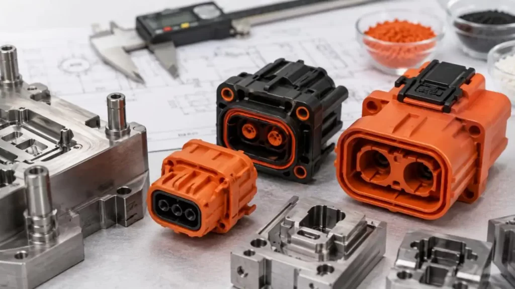
Which Connector Mold Components Need the Tightest Control?
Not every dimension needs micron-level tolerance. The most critical areas usually include:
Terminal Cavity Inserts
These establish pin position, terminal pitch and interface geometry. Positional accuracy relative to functional datums is often more important than an isolated ± tolerance.
Insulation Core Pins
Long or narrow cores form terminal channels, touch-protection recesses and insulation ribs. Their diameter, straightness, unsupported length and support strategy should be evaluated together.
Seal-Groove Inserts
A dimensionally correct groove can still leak if housing warpage changes seal compression. Profile accuracy, flatness and cooling therefore interact.
Shut-Off and Parting Surfaces
These areas directly affect flash. Wear becomes especially important around terminals and sealing interfaces.
Steel, Carbide or Replaceable Inserts?
Material and manufacturing routes should be selected by feature rather than choosing one solution for the complete mold.
| Option | Main Advantage | Main Limitation | Best Use |
| Tool steel | Toughness and repairability | Lower wear resistance than carbide | General inserts and complex features |
| Carbide | Excellent abrasion resistance | Higher cost and chipping sensitivity | High-wear small cores |
| Integral cavity | High structural rigidity | Difficult local repair | Stable, less wear-sensitive geometry |
| Replaceable insert | Easy replacement and dimensional recovery | Requires accurate fitting | Terminal zones and wear-critical details |
This logic can also be applied to manufacturing processes. EDM is quite useful for producing deep slots and intricate internal shapes. Grinding, on the other hand, achieves high precision in surface straightness, surface quality, and dimensional control. High-quality Connector Mold Components usually require both processes. Thus, it is inappropriate to consider EDM and grinding as competing processes.
Cooling also requires comparison. Conventional drilled channels are economical and maintainable, while conformal cooling can improve temperature uniformity around complex housings. However, conformal cooling increases tooling complexity and is not automatically justified for every connector.
Resin Selection Changes the Tooling Strategy
Connector material cannot be separated from mold design.
PBT-GF, PA66-GF, PPS and LCP differ in flow behavior, molding temperature, shrinkage and dimensional response. Higher glass-fiber content can improve molded-part stiffness but also accelerates abrasion of Connector Mold Components.
Material selection therefore influences:
•Gate wear
•Vent and shut-off condition
•Cavity compensation
•Cooling balance
•Warpage behavior
•Surface treatment
•Insert replacement frequency
Thin-wall PPS or LCP structures may benefit from strong flow characteristics, but narrow cavities and flash-sensitive interfaces demand precise shut-offs and controlled venting. PBT-GF or PA66-GF housings may introduce different shrinkage and fiber-orientation effects. Tooling decisions must follow the actual resin grade and geometry.
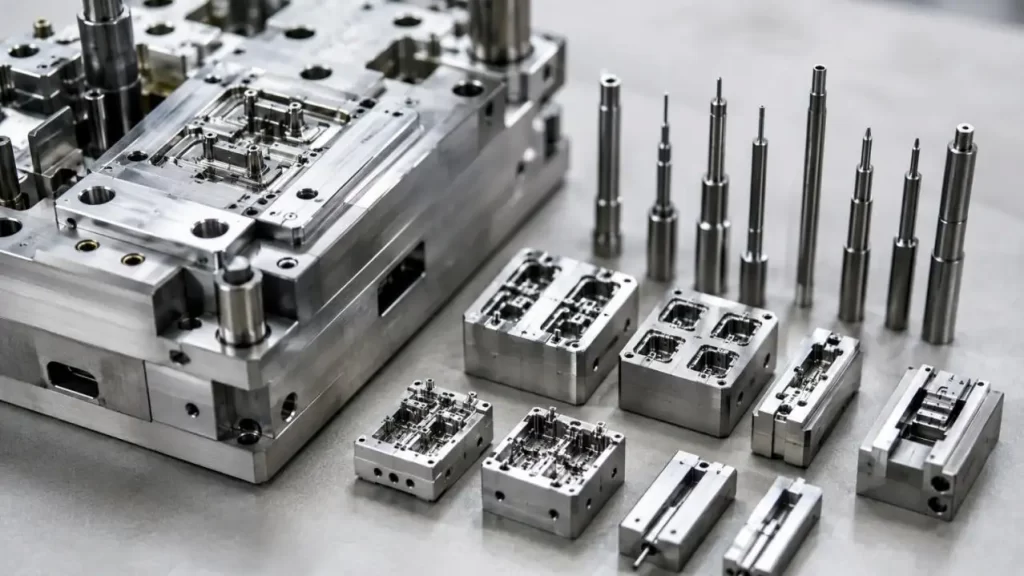
Match the Mold to the Complete High-Voltage Connector System
A supplier should not evaluate Connector Mold Components from the plastic drawing alone. Battery, PDU, inverter and motor connectors can impose different current, temperature, vibration, shielding and sealing requirements.
Before finalizing tooling, engineers should know:
•Operating voltage and current
•Plastic resin and glass-fiber content
•Terminal layout
•HVIL architecture
•Shielding requirement
•Sealing target
•Operating temperature
•Annual production volume
•Cavity quantity
•Expected mold life
For example, KT TOOL combines precision mold development with CAE-supported forming and precision machining in connector projects. For an aluminum alloy connector spring-contact project, 5052/6061 material at 0.2–0.4 mm thickness was produced by multi-station progressive stamping with ±0.02 mm key dimensional tolerance and ≤0.01 mm flatness. Pilot positioning, high-precision guide components and springback compensation were used to maintain repeatability. These figures describe that specific stamped-contact project and should not be interpreted as universal tolerances for every high-voltage mold component.
Design Connector Mold Components for Maintenance, Not Only First-Off Samples
Automotive tooling must remain serviceable after extended production.
Replaceable terminal inserts, standardized datums and controlled fitting surfaces can allow worn Connector Mold Components to be replaced without rebuilding the entire cavity. A preventive maintenance plan should track:
•Core-pin wear or bending
•Shut-off deterioration
•Gate erosion
•Parting-line damage
•Dimensional drift
•Cavity-to-cavity variation
Critical spare inserts should be defined before mass production. Interchangeability should also be verified through measurement rather than assumed from CAD dimensions.
Validate the Connector, Not Just the Mold
Mold inspection is only the first level of validation.
The verification chain should be:
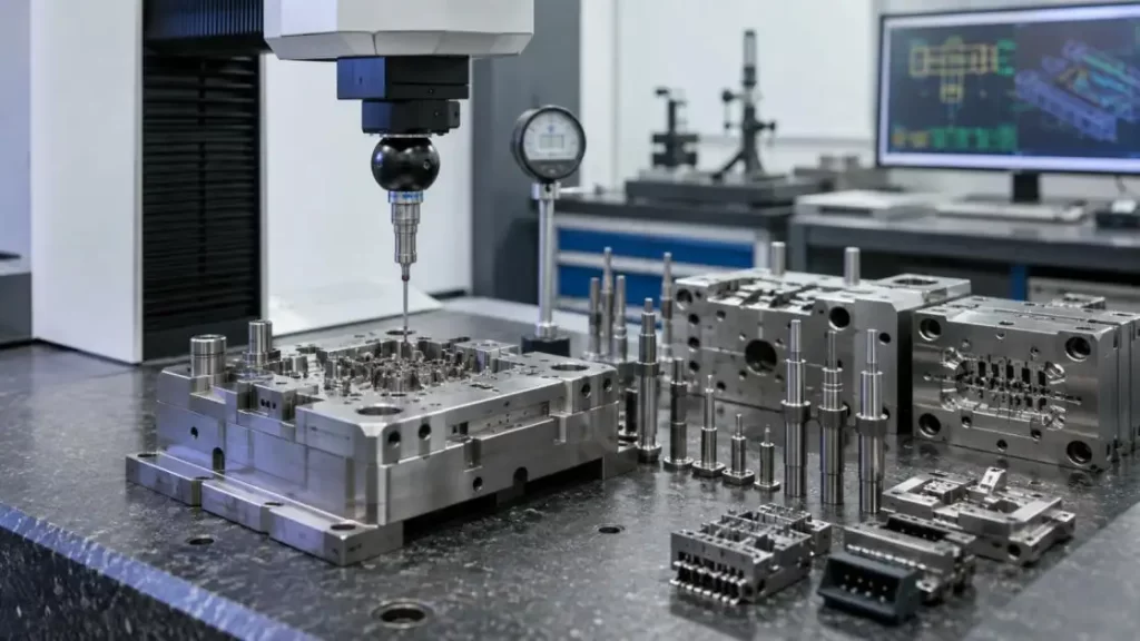
Connector Mold Component inspection → molded housing inspection → assembled connector approval.
ISO 6469-3:2021 and ISO 21498-2:2024 concern class B electric propulsion circuits and components. ISO 20653:2023 describes a standard for a methodology to define and test the IP protection of vehicle electrical equipment.
The mechanical environment is also significant. ISO 16750-3:2023 describes mechanical loads for vehicle electrical and electronic systems, and equipment of applicable voltage class B.
These standards cover systems or components, not the mold. Therefore, claims of "IP6K9K-certified mold components" should be avoided.
Final Words
For connector programs requiring both tooling development and precision metal components, KT TOOL can support engineering review, precision mold development, CAE-assisted process optimization, machining and progressive stamping. Our connector-contact experience also includes automated punching, bending and shaping with online dimensional control. Providing the application, material, drawings and production requirements at the RFQ stage allows the engineering team to evaluate the appropriate Connector Mold Components and manufacturing route before production begins.
FAQs
Q1. What Connector Mold Components does KT TOOL offer?
KT TOOL creates custom precision mold components, including mold inserts, core pins, cavity components, locating elements, guide elements, and additional tooling components. The manufacturing route will include precision machining, EDM, grinding, and inspection, depending on the component geometry.
Q2. Does KT TOOL support Connector Mold Components for automotive applications?
Connector Mold Components for automotive applications are offered by KT TOOL. Connector Mold Components including connector positioning for connector/automotive applications with a focus on mass production and wear resistance are supported. Final specifications for material, tolerances, and tooling will be based on the actual connector design.
Q3. Can KT TOOL manufacture mold components for high-voltage connector housings?
Connector Mold Components for high-voltage connector housings, including cavities for terminals, insulation, sealing features, and other precision molding components, can be supported by KT TOOL. During DFM review, sealing, spacing, and terminal layouts as well as production quantity and other requirements will be considered.
Q4. How does KT TOOL select materials for Connector Mold Components?
Material choice will be influenced by component design, expected wear, type of resin used, and production volume with consideration of repair. A good compromise of toughness and machinability is offered by tool steels. It is possible to consider carbide for very high-wear applications.
Q5. Can KT TOOL produce replaceable precision mold inserts?
Yes. Terminal cavities and shut-offs can include replaceable inserts, as can other Connector Mold Components. This design allows for easier maintenance since the entire cavity does not need to be replaced when wear is localized.
Talk to the Manufacturer, Not a Middleman
Resources & Insights
-
 Industry Insights
CNC Machining Robotic Parts: How GD&T Controls Robot Assembly Accuracy
2026-09-24By KT Engineering -
 Industry Insights
Hardware Stamping Springback Control for High-Strength Steel Parts
2026-09-24By KT Engineering -
 Industry Insights
Spring Stamping Fatigue Life: How Geometry, Material and Edge Quality Affect Cycle Life
2026-09-24By KT Engineering -
 Industry Insights
Mechanical Automation Parts for Robot End Effectors and Positioning Accuracy
2026-09-23By KT Engineering