Contact Us
 Home /
Automation Machining for Pneumatic Manifolds: Port Accuracy & Flow


Table of Contents
- Port Accuracy Is a Functional Requirement, Not Just a Drawing Dimension
- Sealing Depends on More Than Thread Accuracy
- Internal Flow Design Can Become the Hidden Bottleneck
- Four Automation Machining Decisions That Change Manifold Performance
- Deburring and Cleaning Are Part of Manifold Manufacturing
- Dimensional Inspection and Functional Validation Solve Different Problems
- What Buyers Should Define Before Requesting Automation Machining

A pneumatic manifold is not simply a metal block with drilled ports. In an automated machine, it becomes the interface between valves, fittings, tubing, cylinders, grippers, and the compressed-air supply. Small errors in port position, sealing geometry, or internal passages can therefore appear as leakage, slow actuator response, unstable pressure, or difficult valve assembly.
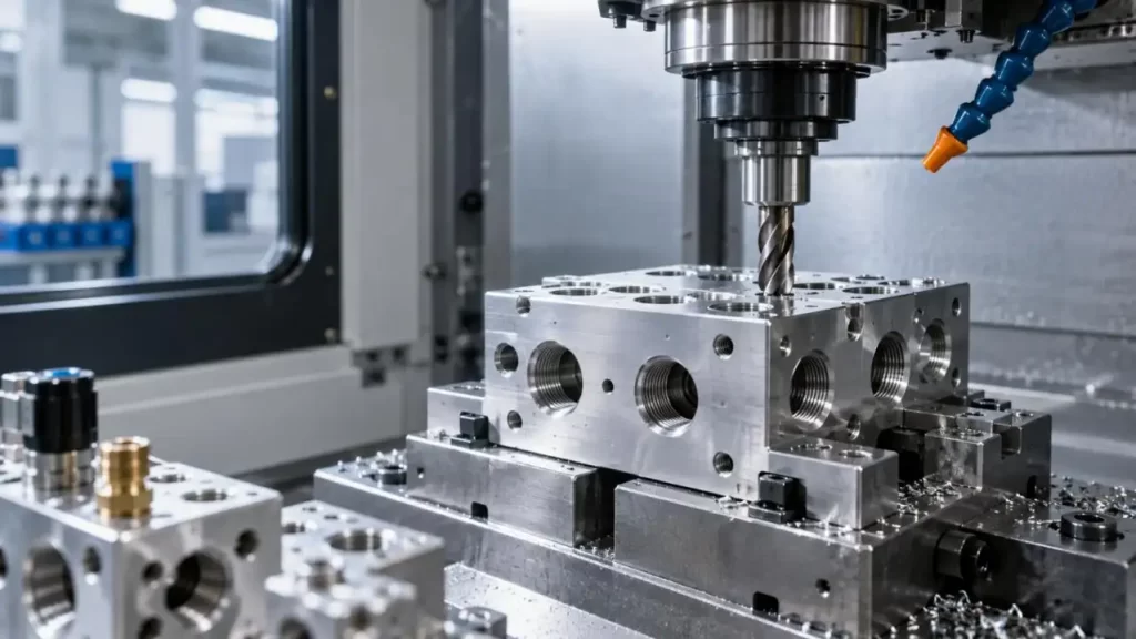
For Automation Machining, the engineering challenge is to control the features that influence function—not to apply an unnecessarily tight tolerance to every dimension.
At KT, this distinction is important when reviewing pneumatic manifolds and other automation parts. Our CNC capability covers standard machining tolerances around ±0.05 mm and high-precision machining down to ±0.005 mm where material, geometry, fixturing, and process conditions allow. Complex 5-axis components can reach tighter capability levels when the application requires them.
Port Accuracy Is a Functional Requirement, Not Just a Drawing Dimension
A manifold may have the correct individual hole diameters but still fail during assembly. What matters is the relationship between the ports, mounting features, and reference datums.
Critical features typically include:
| Feature | Functional Effect | Typical Failure |
| Port position | Aligns valves and fittings | Assembly interference |
| Port pitch | Controls multi-valve alignment | Cumulative mismatch |
| Counterbore depth | Locates sealing interface | Uneven seal compression |
| O-ring groove | Controls elastomer squeeze | Leakage or extrusion |
| Sealing-face flatness | Maintains contact pressure | Local air leakage |
| Thread depth | Controls fitting engagement | Weak or inconsistent joint |
In Automation Machining, these dimensions should be related to functional datums rather than treated as isolated ± dimensions.
A common mistake is specifying ±0.005 mm everywhere because "higher precision is better." It is not. Unnecessary tolerances increase machining time, inspection requirements, tooling sensitivity, and cost without improving manifold performance. KT applies the same principle in tolerance planning: tight control should be concentrated on functional features.
Video link: https://youtube.com/shorts/RWeWAUdh2PQ?feature=share
Sealing Depends on More Than Thread Accuracy
The first question should be: where does the joint actually seal?
A tapered threaded port may depend on thread engagement and the specified sealing method. A parallel-thread connection may instead use an O-ring, washer, or dedicated sealing face.
For O-ring interfaces, engineers must consider:
• Groove depth and width;
• O-ring cross-section;
• Sealing-face flatness;
• Surface condition;
• Compression under assembly;
• Pressure and temperature conditions.
ISO 3601-2:2025 specifies O-ring housing dimensions for general hydraulic and pneumatic applications, reinforcing that groove geometry and the mating surface are part of the sealing system—not secondary machining details.
This is why Automation Machining for pneumatic manifolds should distinguish between thread accuracy and seal-interface accuracy.
Internal Flow Design Can Become the Hidden Bottleneck
Nominal fitting size does not define actual manifold flow.
The pneumatic path may be:
Supply Port → Main Gallery → Cross-Hole → Valve → Tube → Actuator
If one cross-hole is significantly smaller than the surrounding passages, it can become the effective restriction. Passage length, diameter changes, intersections, and sharp turns also influence pressure loss and actuator response.
For a manifold feeding several cylinders simultaneously, engineers should evaluate:
• Required peak airflow;
• Number of actuators moving at the same time;
• Valve and tubing capacity;
• Smallest internal passage;
• Acceptable pressure drop;
• Cylinder speed requirements.
A G1/2 inlet, for example, does not automatically make a manifold "high flow" if the internal branches are much smaller.
Four Automation Machining Decisions That Change Manifold Performance
Different manifold architectures require different manufacturing strategies.
| Engineering Decision | Option A | Option B | Main Trade-Off |
| Internal gallery | Straight passages | Cross-drilled passages | Flow simplicity vs compact packaging |
| Machining method | 3-axis, multiple setups | 5-axis machining | Lower cost vs reduced datum transfer |
| Port sealing | Thread-dependent seal | O-ring / face seal | Installation sensitivity vs seal-geometry control |
| Flow layout | Larger internal passages | Compact passages | Lower restriction vs wall thickness and size |
Straight vs. Cross-Drilled Passages
Cross-drilling allows several ports to be connected inside a compact manifold, but every intersection creates additional manufacturing considerations.
Typical risks include:
• Burrs at hidden intersections;
• Chips trapped in internal galleries;
• Access holes that require plugging;
• More abrupt airflow direction changes.
Straight passages are easier to machine and inspect, but can require a larger manifold envelope.
3-Axis vs. 5-Axis Automation Machining
Simple rectangular manifolds can often be produced efficiently using 3-axis machining and controlled re-fixturing.
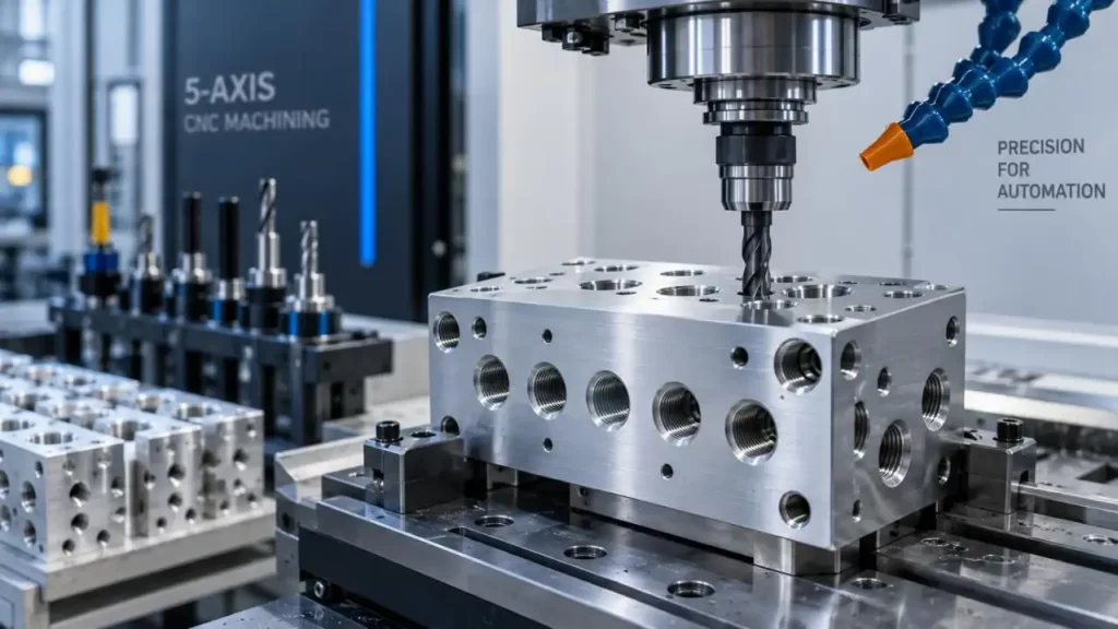
For manifolds with ports on several faces, angled features, or closely related positional tolerances, 5-axis machining can reduce the number of setups and therefore reduce datum-transfer error.
KT operates more than 30 machining centers covering 3-axis milling through simultaneous 5-axis machining, including equipment from DMG MORI, Mazak, Haas, and Fanuc.
The engineering question is not whether 5-axis is "better," but whether fewer setups improve the accuracy of critical feature relationships.
Deburring and Cleaning Are Part of Manifold Manufacturing
For pneumatic manifolds, the machining cycle is not finished when the final hole is drilled.
Cross-hole intersections need particular attention because an internal burr can:
• Partially block airflow;
• Detach during operation;
• Contaminate a solenoid valve;
• Damage downstream pneumatic components.
A suitable production plan should therefore consider internal deburring, chip removal, passage cleaning, thread protection, and sealing-face protection during surface finishing.
ISO 4414 also treats cleaning, maintenance, installation, reliable operation, and system safety as relevant aspects of pneumatic fluid-power systems.
Dimensional Inspection and Functional Validation Solve Different Problems
A CMM can verify port position, datum relationships, flatness, and other geometric characteristics. Thread gauges can verify threaded interfaces.
Neither measurement alone proves that the completed pneumatic circuit will meet its leakage or flow requirement.
A robust inspection strategy may separate:
Dimensional Verification
• Port position and pitch;
• Mounting-hole location;
• Critical bore diameters;
• Sealing geometry;
• Threads and GD&T.
Functional Verification
• Pressure integrity;
• Leakage requirement;
• Passage continuity;
• Flow performance where specified.
KT uses advanced dimensional inspection methods including CMM and process monitoring to support tolerance control from machining through final inspection.
What Buyers Should Define Before Requesting Automation Machining
A useful pneumatic manifold RFQ should provide more than a STEP file.
Include:
• 2D drawing with functional datums;
• 3D CAD model;
• Aluminum, stainless steel, or other material;
• Port and thread standards;
• O-ring or sealing specifications;
• Working pressure;
• Critical GD&T;
• Surface treatment;
• Required inspection documentation;
• Prototype and production quantities.
KT already manufactures pneumatic manifolds, robotic gripper fingers, linear guide rails, and sensor brackets for automation applications, supporting both precision components and small-batch, high-variety automation requirements.
Accurate Automation Machining begins with the understanding of a manifold's purpose in a pneumatic system. From understanding accurate machining, fixturing, deburring, and inspection processes is a start. If you are designing a pneumatic manifold, KT would review your 2D and 3D designs and specify potential CNC machining processes along with tolerances for production.
FAQs
Q1. Does KT provide Automation Machining for pneumatic manifolds?
Yes. KT lists pneumatic manifolds among its automation machining applications, together with robotic gripper fingers, linear guide rails, and sensor brackets.
Q2. What machining accuracy can KT achieve for automation parts?
KT lists standard CNC machining capability around ±0.05 mm and high-precision machining capability down to ±0.005 mm under suitable material, geometry, tooling, and setup conditions. Actual tolerances should always be defined according to the functional feature.
Q3. Can KT machine multi-face pneumatic manifolds?
Yes. KT operates 3-axis, 4-axis, and simultaneous 5-axis CNC equipment, allowing multi-face ports, mounting features, and complex manifold geometries to be produced with fewer setups where appropriate.
Q4. When does KT recommend 5-axis Automation Machining for a manifold?
5-axis machining is particularly useful when ports are located on several faces, when angled holes are required, or when reducing datum-transfer error between multiple setups is important.
Q5. Can KT machine O-ring grooves and sealing surfaces?
Yes. These features can be incorporated into CNC machining according to the customer's drawings, seal specifications, surface requirements, and functional tolerances.
Talk to the Manufacturer, Not a Middleman
Resources & Insights
-
 Industry Insights
CNC Machining Robotic Parts: How GD&T Controls Robot Assembly Accuracy
2026-09-24By KT Engineering -
 Industry Insights
Hardware Stamping Springback Control for High-Strength Steel Parts
2026-09-24By KT Engineering -
 Industry Insights
Spring Stamping Fatigue Life: How Geometry, Material and Edge Quality Affect Cycle Life
2026-09-24By KT Engineering -
 Industry Insights
Mechanical Automation Parts for Robot End Effectors and Positioning Accuracy
2026-09-23By KT Engineering