Contact Us
 Home /
Smart Locker Enclosure Components: IP Protection, Drainage and Corrosion Control


Table of Contents
- Water Usually Enters Through Interfaces, Not Panels
- Gasket Compression Must Be Designed Around Real Production Tolerances
- Drainage Is a Geometry Problem, Not Simply a Drain-Hole Problem
- Material Selection Must Consider the Entire Corrosion System
- Electronic Locks and HMI Openings Change the Enclosure Design
- Welding Distortion and Coating Build-Up Must Be Included in the Tolerance Stack
- Installation and Maintenance Affect Long-Term Protection
- Verify IP and Corrosion Requirements Separately

Outdoor smart lockers operate differently from indoor cabinets. Rain, humidity, temperature cycling, dust and repeated door operation all affect enclosure reliability. In practice, most failures do not start in the middle of a sheet-metal panel. They begin at interfaces: door gaps, lock openings, hinges, display cutouts, cable entries and welded corners.
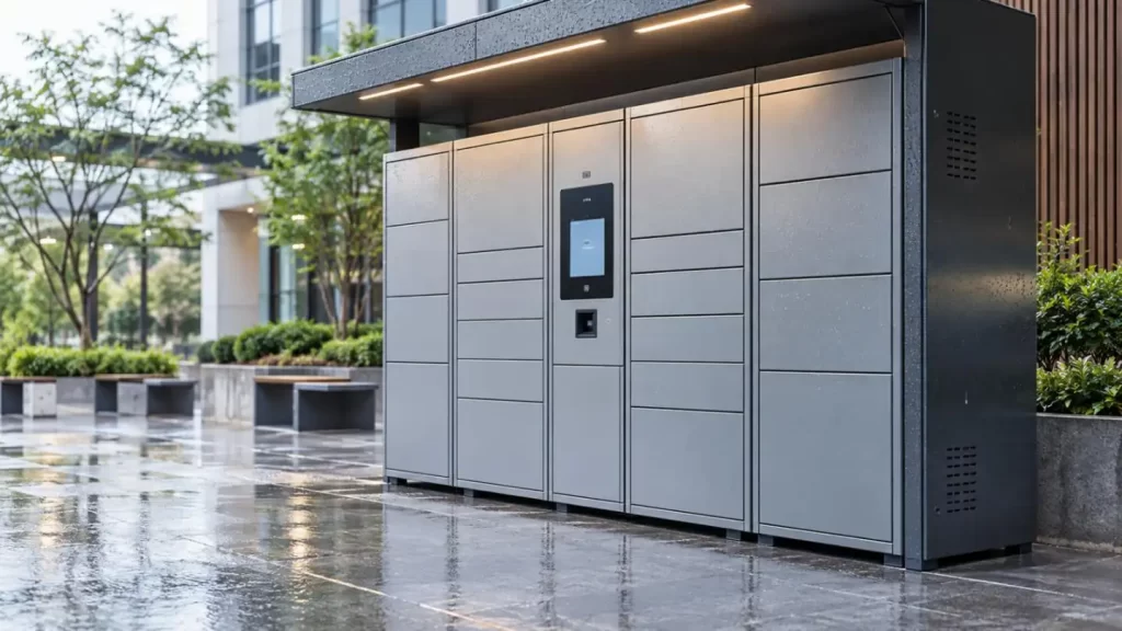
For this reason, reliable Smart Locker Enclosure Components should be engineered around three linked requirements:
•Ingress protection: Control direct rain and splash.
•Drainage: Remove water that reaches secondary enclosure zones.
•Corrosion control: Prevent long-term degradation at edges, welds and fastener interfaces.
The enclosure only performs correctly when these functions are combined with controlled manufacturing tolerances.
Water Usually Enters Through Interfaces, Not Panels
A locker door may appear closed while still having local sealing gaps. Long sheet-metal doors can bow between latch points, while welding or bending variation can distort the frame.
The sealing chain is therefore:
Frame Geometry → Door Flatness → Latch Position → Gasket Compression → Water Resistance
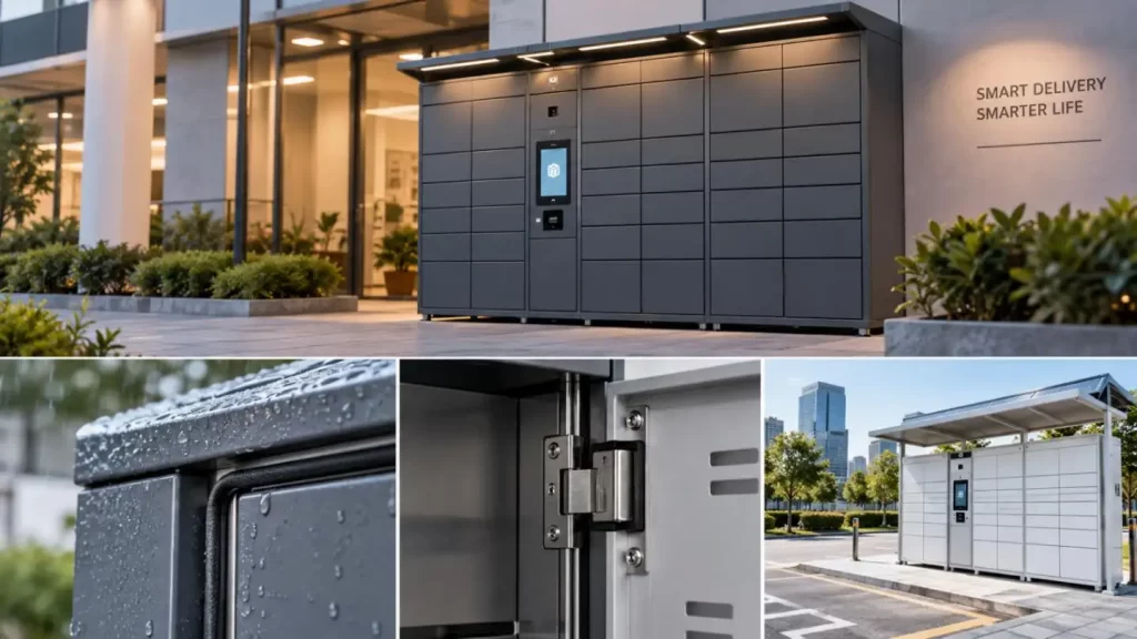
Typical vulnerable areas in Smart Locker Enclosure Components include:
•Door-to-frame interfaces
•Electronic lock and strike openings
•Hinge mounting holes
•Screen and scanner cutouts
•Cable glands and power-entry points
•Horizontal seams
•Welded corners and low collection points
IEC 60529 evaluates ingress protection at the enclosure level. A metal part or gasket alone therefore should not be described as "IP65" without testing the completed assembly.
https://youtube.com/shorts/dg7KIKICSCg?feature=share
Gasket Compression Must Be Designed Around Real Production Tolerances
A gasket does not compensate for unlimited dimensional error.
If the nominal door gap is correct but the panel is locally warped, compression may vary significantly around the perimeter. Too little compression can create a leak path; excessive compression may increase closing force and accelerate gasket deformation.
Critical dimensions normally include:
•Door flatness
•Frame squareness
•Hinge location
•Latch-to-strike position
•Hole-to-bend distance
•Gasket contact width
•Gap consistency around the door
KT offers a typical sheet-metal fabrication tolerance of ±0.1 mm, with ±0.05 mm high-precision capability for suitable thin-sheet applications. For machined interfaces, its stated CNC machining capability is typically ±0.05 mm with tighter tolerances available for appropriate features. Actual tolerances should still be assigned according to material, geometry and function rather than applied uniformly across the enclosure.
Drainage Is a Geometry Problem, Not Simply a Drain-Hole Problem
Outdoor Smart Locker Enclosure Components should not rely on a single seal as the only defense against water.
A more advanced architecture combines:
- A primary gasket or overlapping barrier.
- A drip edge to minimize water impact.
- A secondary channel behind the first barrier.
- A gravity drainage path to the lowest point.
A drain hole positioned above the actual collection point may leave standing water inside a folded section. Likewise, inward-facing hems or horizontal ledges can create unintended reservoirs.
Two Water-Control Strategies
| Design Approach | Main Advantage | Main Risk |
| Seal-Dominant Joint | Simple water barrier | Highly sensitive to gasket condition and door distortion |
| Labyrinth + Drainage | Manages secondary water entry | Requires more deliberate geometry |
| Higher-Sealing Design | Suitable for demanding exposure | Higher tolerance, sealing and condensation requirements |
A higher IP target is not automatically the better engineering choice. Environmental exposure, electronics, thermal behavior and maintenance access should determine the protection strategy.
Material Selection Must Consider the Entire Corrosion System
Different Smart Locker Enclosure Components require different material strategies.
| Material | Strength | Main Corrosion Concern | Typical Outdoor Strategy |
| Carbon Steel | High stiffness, economical | Exposed steel after coating damage | Pretreatment + powder coating |
| Stainless Steel | High inherent corrosion resistance | Crevice/chloride conditions | Proper grade and surface finish |
| Aluminum | Low weight | Galvanic interaction with dissimilar metals | Anodizing/coating + compatible fasteners |
KT's sheet-metal facility processes stainless steel, aluminum, cold-rolled steel and copper from 0.5 to 12 mm, using laser cutting, press braking, punching, spot welding, TIG/MIG welding and hardware insertion. Parts can also be powder-coated, anodized or plated to specification.
Pay Special Attention to Edges and Welds
Corrosion often develops first at:
•Laser-cut or sheared edges
•Weld heat-affected zones
•Scratched coating areas
•Drainage low points
•Fastener interfaces
•Crevices between overlapping sheets
For coated carbon steel, surface treatment should therefore be reviewed as part of enclosure engineering—not added as an isolated finishing step.
Electronic Locks and HMI Openings Change the Enclosure Design
Smart lockers differ from conventional cabinets because the enclosure must integrate electronics.
Typical interfaces include:
•Electronic locks
•Touchscreens
•Barcode scanners
•RFID readers
•Cameras
•Indicator lights
•Antennas
•Power and communication cables
Each opening interrupts the original water barrier.
For example, an electronic lock requires both accurate cutout geometry and correct strike alignment. A position error can prevent full door closure, which then changes gasket compression.
Where tighter local interfaces are required, CNC-machined brackets, lock plates or sensor mounts may be combined with fabricated Smart Locker Enclosure Components. KT reports CNC machining down to ±0.005 mm for suitable high-precision features, depending on the material, geometry and setup.
Welding Distortion and Coating Build-Up Must Be Included in the Tolerance Stack
A CAD model may show perfect alignment, but production adds several sources of variation:
Laser Cutting → Bending → Welding → Hardware Insertion → Finishing → Final Assembly
Welding can change frame squareness. Powder coating can add material around hinge or latch interfaces. Multiple bend tolerances can accumulate across tall locker modules.
For this reason, critical interface dimensions should be separated from general cosmetic dimensions.
Recommended controls include:
•Datum-based inspection
•Door-gap checks after welding
•Flatness inspection
•Lock and hinge fixture verification
•Coating allowance on mating interfaces
•Final functional opening/closing tests
KT's sheet-metal capability combines cutting, bending, welding and hardware insertion, while its DFM process reviews issues such as bend-radius conflicts and weld access before fabrication.
Installation and Maintenance Affect Long-Term Protection
Even correctly manufactured Smart Locker Enclosure Components can lose performance after installation.
An uneven base may twist a tall cabinet and change door alignment. Drain channels can collect debris. Gaskets may develop compression set or mechanical damage.
Routine inspection should therefore cover:
•Door gap and latch alignment
•Gasket continuity
•Drain-channel blockage
•Coating damage
•Fastener loosening
•Standing water around lower folds
Verify IP and Corrosion Requirements Separately
Ingress protection and corrosion resistance should not be treated as the same test.
IP requirements evaluate protection against solid objects and water ingress, while corrosion specifications may use separate salt-spray or environmental exposure standards. Salt-spray hours should also not be converted directly into a guaranteed number of outdoor service years.
A professional RFQ for Smart Locker Enclosure Components should therefore define:
•Installation environment
•Target ingress requirement
•Material and sheet thickness
•Surface-treatment system
•Critical door and lock tolerances
•Gasket interface
•Drainage geometry
•HMI and cable cutouts
•Corrosion-test requirements
•Prototype and production inspection criteria
From Outdoor Enclosure Design to Stable Production
Reliable Smart Locker Enclosure Components are not created by simply increasing sheet thickness or adding a stronger gasket. The design must control how water reaches the enclosure, how it is blocked or drained, how corrosion is managed, and how production variation affects sealing interfaces.
KT integrates fabrication, machining, welding, hardware and finishing for chassis manufacturing processes. Sharing 2D, 3D models, important sealing interfaces, and environmental data with KT at the early stages of Smart Locker development allows the team to evaluate manufacturability, tolerances, and risks of production.
For detailed discussions on custom Smart Locker enclosures, contact KT to provide drawings and select materials for the enclosures as well as other requirements of the production process.
FAQs
Q1. Can KT offer custom Smart Locker Enclosure Components?
Yes. KT supports custom Smart Locker Enclosure Components based on customer drawings, 3D models and functional requirements, including panels, doors, brackets, lock plates and internal mounting parts.
Q2. What materials can KT use for Smart Locker Enclosure Components?
KT works with materials commonly used for outdoor enclosures, including stainless steel, aluminum and cold-rolled steel. Material selection can be matched to corrosion resistance, weight, stiffness and cost requirements.
Q3. What sheet thicknesses can KT process?
KT’s sheet metal manufacturing capabilities cover approximately 0.5 mm to 12 mm sheet thicknesses, depending on material and fabrication process.
Q4. What manufacturing processes are available for Smart Locker Enclosure Components?
Available processes include:
•CNC laser cutting
•CNC bending
•Punching
•Stamping
•Spot welding
•TIG/MIG welding
•Hardware insertion
•CNC machining
These processes can be combined for complex smart locker assemblies.
Q5. What tolerance can KT achieve for sheet metal components?
KT offers typical sheet-metal fabrication tolerances around ±0.1 mm, with ±0.05 mm capability for suitable high-precision thin-sheet applications. Final tolerances depend on geometry, material and manufacturing sequence.
Talk to the Manufacturer, Not a Middleman
Resources & Insights
-
 Industry Insights
CNC Machining Robotic Parts: How GD&T Controls Robot Assembly Accuracy
2026-09-24By KT Engineering -
 Industry Insights
Hardware Stamping Springback Control for High-Strength Steel Parts
2026-09-24By KT Engineering -
 Industry Insights
Spring Stamping Fatigue Life: How Geometry, Material and Edge Quality Affect Cycle Life
2026-09-24By KT Engineering -
 Industry Insights
Mechanical Automation Parts for Robot End Effectors and Positioning Accuracy
2026-09-23By KT Engineering