Contact Us
  Home /
 Machining Part Design for Manufacturability: 10 DFM Rules for CNC Components


Table of Contents
- What Does DFM Mean for a Machining Part?
-
10 DFM Rules for Machining Part Design
- RULE 1. Apply Tight Tolerances Only to Functional Features
- RULE 2. Increase Internal Corner Radii Where Possible
- RULE 3. Control Pocket Depth-to-Width Ratio
- RULE 4. Avoid Unnecessarily Thin Walls
- RULE 5. Use Standard Hole and Thread Sizes
- RULE 6. Reduce Setup and Datum Transfers
- RULE 7. Design for Real Tool Accessibility
- RULE 8. Specify Surface Roughness by Function
- RULE 9. Include Surface Treatment in the Drawing Strategy
- RULE 10. Make the Machining Part Measurable
- How Material Changes Machining Part DFM
- From Prototype to Production at KT TOOL

A CAD model of a Machining Part is not necessarily easy or cost-effective to manufacture. It would be the case for a design with deep pockets, thin walls, sharp internal corners, hard-to-reach features, and tight tolerances. Such a design could lead to an increased risk of scrappage, increased deflection of the tooling, extended setup and time, and increased inspection due to the risk of failing to meet specifications.
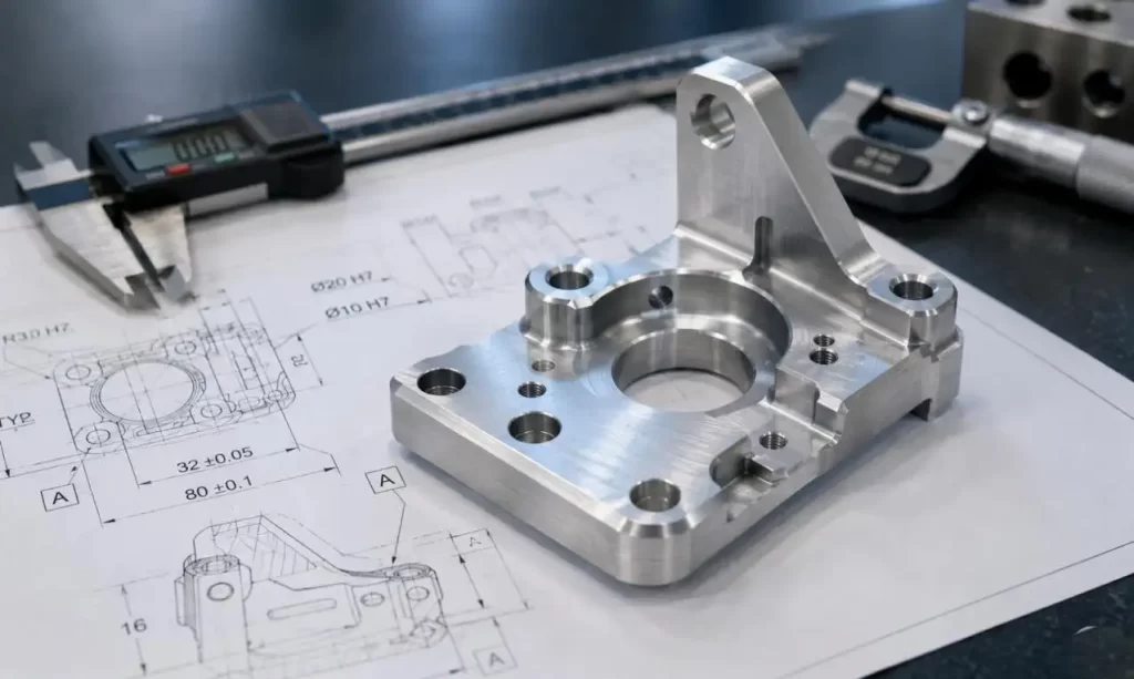
Design for Manufacturability (DFM) helps to avoid the situations mentioned above before the design gets to the stage of machining. For a precision Machining Part, effective DFM means optimizing the balance of the design, specific materials, tolerances, accessibility, surface finish, inspection, and the expected production volume instead of setting the specification value to the minimum.
What Does DFM Mean for a Machining Part?
Adapting the design of a Machining Part to suit the conditions of practical manufacturing, while keeping the required functionality of the part, is what DFM is all about.
A CNC DFM review typically examines:
• Tool access and cutter reach
• Wall and rib thickness
• Pocket depth and width
• Internal corner radius
• Hole diameter and depth
• Datum relationships
• Dimensional and geometric tolerances
• Surface roughness
• Material machinability
• Coating or finishing allowance
• Inspection accessibility
• Prototype versus production quantity
| Design Factor | Manufacturing Effect |
| Tight tolerance | More controlled machining and inspection |
| Thin wall | Higher deformation and chatter risk |
| Deep pocket | Longer tools and lower rigidity |
| Small corner radius | Smaller cutters and longer cycle time |
| Multiple datums | More setup and alignment complexity |
| Low surface roughness | Additional finishing passes |
| Hard-to-machine material | Higher heat and tool wear |
The objective is not to remove precision. It is to apply precision where the Machining Part actually needs it.
10 DFM Rules for Machining Part Design
RULE 1. Apply Tight Tolerances Only to Functional Features
Specifying uniform tolerances of ±0.01 mm across an entire part drawing creates excessive and arbitrary machining and inspection.
While tolerances may be wider on some general features, tolerances must be tighter on bearing seats, locating holes, sealing surfaces, and other interfaces and mated features.
As a standard, KT TOOL applies ±0.1 mm and may apply tighter tolerances based on the feature geometry, manufacturing process, and inspection method.
DFM principle: Connect every critical tolerance to a functional requirement.
RULE 2. Increase Internal Corner Radii Where Possible
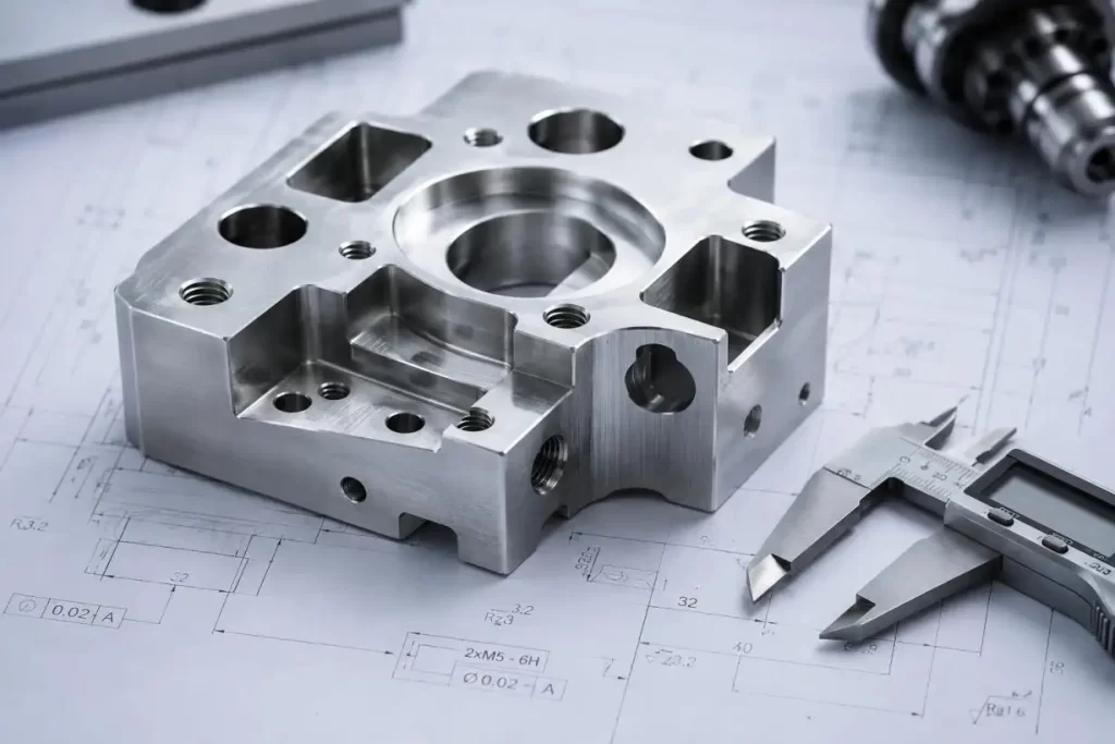
CNC milling cutters are cylindrical, so a milled internal corner naturally contains a radius.
Very small corner radii require smaller cutters, which generally have:
• Lower rigidity
• Reduced material removal rates
• Greater deflection risk
• Longer cycle times
A larger internal radius allows a larger, more rigid tool and more stable cutting. Square internal corners should therefore be specified only when the assembly genuinely requires them.
RULE 3. Control Pocket Depth-to-Width Ratio
A deep, narrow pocket is one of the more difficult features on a Machining Part.
Long-reach tools can introduce:
• Chatter
• Cutter deflection
• Chip evacuation problems
• Reduced feed rates
• Uneven wall finish
Designers should widen cavities or reduce depth where function permits. Deep cavities may also require multiple tool lengths or alternative machining strategies.
RULE 4. Avoid Unnecessarily Thin Walls
Thin walls can move during machining because material is progressively removed around them.
Major influences include:
• Cutting force
• Fixture pressure
• Cutting heat
• Residual material stress
• Wall height
• Material stiffness
Stainless steel generally produces higher cutting loads than aluminum, while engineering plastics can respond strongly to heat and clamping pressure.
For a thin-wall Machining Part, machining sequence and fixture strategy should be considered during design rather than after deformation appears.
RULE 5. Use Standard Hole and Thread Sizes
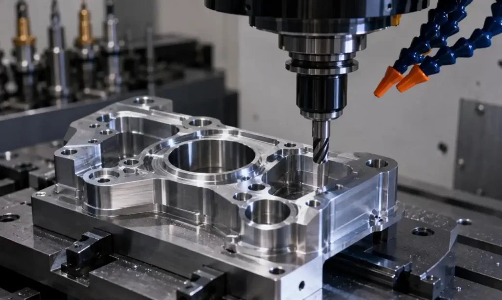
Standard tooling usually provides the simplest route to repeatable holes.
Avoid where possible:
• Unusual hole diameters
• Small holes with extreme depth
• Threads running to the bottom of blind holes
• Very thin material around threaded features
Different requirements may call for different processes:
• Drilling: general hole production
• Reaming: improved hole size and finish
• Boring: controlled diameter and position
• Threading: internal or external fastening features
Hole tolerance should be defined by assembly function, not by default.
RULE 6. Reduce Setup and Datum Transfers
Each time a Machining Part is repositioned, relationships between machined features must be re-established.
Additional setups can increase:
• Datum-transfer error
• Fixture variation
• Alignment time
• Inspection workload
Critical bores, faces, and locating features should share practical datums wherever possible. Features with strict positional relationships are preferably machined within the same setup when geometry permits.
RULE 7. Design for Real Tool Accessibility
CAD software can create geometry that a cutting tool cannot easily reach.
Typical problems include:
• Hidden side holes
• Narrow internal slots
• Undercuts
• Deep recessed features
• Tool interference with nearby walls
Depending on geometry, a Machining Part may require 3-axis milling, 4-axis or 5-axis machining, turning, mill-turn processing, or EDM.
More axes do not automatically mean a better process. The correct route depends on feature access, tolerance relationships, batch quantity, and cost.
RULE 8. Specify Surface Roughness by Function
A lower Ra value generally requires more controlled finishing.
KT TOOL supports surface roughness requirements in approximately the Ra 0.2–Ra 3.2 μm range depending on the feature and process.
| Surface Type | DFM Consideration |
| Structural surface | Standard machined finish may be sufficient |
| Sliding interface | Lower roughness may reduce friction |
| Sealing surface | Finish must support sealing function |
| Cosmetic surface | Brushing or polishing may be specified |
| Coated surface | Pretreatment and coating must be considered |
Applying a very low Ra requirement to every face of a Machining Part can add machining time without improving function.
RULE 9. Include Surface Treatment in the Drawing Strategy
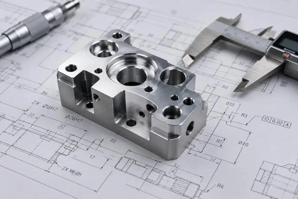
Finishing is an aspect of dimensional design.
Processes that may be available include:
• Brushing
• Polishing
• Anodizing
• Electroplating
• Powder Coating
• Silk-screen printing
These processes impact final dimensions, fitting of threads, electrical contacts, protection from corrosion, and aesthetics.
When designing for critical interfaces, engineers should determine if dimensions are to be considered before or after finishing. They should also consider the relevant finishing build up.
RULE 10. Make the Machining Part Measurable
A feature that cannot be inspected reliably creates uncertainty even if it can be machined.
Inspection-oriented DFM considers:
• Accessible datum surfaces
• CMM probe clearance
• Hole measurement access
• Stable measurement locations
• Geometric relationships
• Drawing-defined inspection criteria
KT TOOL uses equipment such as CMMs, height gauges, and laser scanners for dimensional verification. Inspection planning should therefore be linked directly to drawing requirements.
How Material Changes Machining Part DFM
Material selection affects cutting force, heat, tool wear, deformation, and fixture design.
| Material | Machining Behavior | Key DFM Concern |
| Aluminum | Good machinability | Thin-wall movement |
| Stainless Steel | Higher cutting load | Heat and tool wear |
| Brass | Generally machinable | Burr and surface appearance |
| Copper | High thermal conductivity | Burr and tool interaction |
| Titanium | Heat concentrated near cutting zone | Tool life |
| POM | Good machining stability | Clamping |
| Nylon | Moisture-sensitive | Dimensional stability |
| PEEK | High-performance polymer | Heat and material cost |
KT TOOL also processes ABS, polycarbonate, PVC, and other engineering materials according to project requirements.
From Prototype to Production at KT TOOL
A part machined for the prototype stage is primarily for the purposes of testing design, fit, and function. Fixture repeatability, cycle time, tool life, inspection and process efficiencies, and consistency become important as it moves to batch production.
KT TOOL delivers OEM mechanical components as integrated solutions with CNC and processes of laser, cutting, bending, welding, and other sheet metal operations. Additional surface finishing and dimensional inspections may be included.
As a guideline, prototype orders can typically be completed within 5 to 7 days. Batch production can take patterns of up to 14 to 21 days to complete, depending on the complexity of the geometry, type of material, tolerance, finishing, inspection, and quantity.
Designing Machining Parts Around Manufacturing Reality
A well-designed Machining Part encompasses function and geometry, as well as tolerance, material, machining, finishing, inspection, and cost.
During a DFM review, thin-wall features, inaccessible features, excessive or unnecessary tolerances, difficult to machine cavities, problems defining datums, and finishing conflicts can all be identified and resolved prior to production.
With new machining projects, KT TOOL can be provided a 2D drawing along with a 3D CAD file and the required material, quantity, tolerances, surface treatments, and inspection requirements. The engineering team will assess the manufacturability and advise the most effective machining strategy prior to prototyping or production.
FAQs
Q1. What types of parts does KT Tool offer?
KT Tool makes custom Machining Parts for prototypes and both small and large scale productions. Common parts made consist of brackets, housings, structural components, precision mechanical components, and OEM parts for automotive, medical, electronic, robotic, and industrial equipment.
Q2. Which machining methods can be used by KT Tool?
Based on the parts’ geometry and the production needs, KT Tool can use varying methods, such as CNC milling, CNC turning, laser cutting, bending, welding, and other sheet metal fabrication processes and stamping. The manufacturing method will be determined based on the features’ accessibility, required tolerances, the selected material, and quantity.
Q3. What is the best machining tolerance for parts done by KT Tool?
A good tolerance for most features can be around ±0.1 mm, which is a standard. Tighter tolerances can be defined for important mating, locating, and bearing dimensions, and functional requirements considering the geometry, the material selected, the machining method, and the required inspection.
Q4. Which materials can be used for custom machining parts?
KT Tool can use metals such as aluminum, stainless steel, brass, copper, and titanium, along with engineering plastics such as POM, nylon, ABS, PEEK, polycarbonate, and PVC.
Q5. Before machining, can KT Tool do a DFM analysis?
Yes. Before machining, KT Tool can analyze the part drawings for the design features, such as wall thickness, pocket depth, internal radii, hole geometry, tolerances, and the overall part Inspection and surface finish.
Talk to the Manufacturer, Not a Middleman
Resources & Insights
-
 Industry Insights
CNC Machining Robotic Parts: How GD&T Controls Robot Assembly Accuracy
2026-09-24By KT Engineering -
 Industry Insights
Hardware Stamping Springback Control for High-Strength Steel Parts
2026-09-24By KT Engineering -
 Industry Insights
Spring Stamping Fatigue Life: How Geometry, Material and Edge Quality Affect Cycle Life
2026-09-24By KT Engineering -
 Industry Insights
Mechanical Automation Parts for Robot End Effectors and Positioning Accuracy
2026-09-23By KT Engineering