Contact Us
  Home /
 Custom Mould Components for High-Precision Injection Molding Applications


Table of Contents
- What Are Mould Components?
- Why Custom Mould Components Matter
- Functional Tolerances: Tighter Is Not Always Better
- Selecting Materials for Mould Components
- Part Geometry Changes the Engineering Strategy
- CNC, EDM and Grinding for Precision Mould Components
- Heat Treatment and Surface Engineering
- Prototype vs. Mass-Production Mould Components
- Balancing Precision, Tool Life and Cost
- How KT TOOL Approaches Custom Mould Components

High-precision injection molding depends on more than machine repeatability and process settings. The dimensional stability, material properties, surface condition, and assembly accuracy of Mould Components directly influence cavity geometry, flash, ejection, molded-part dimensions, and long-term production consistency.
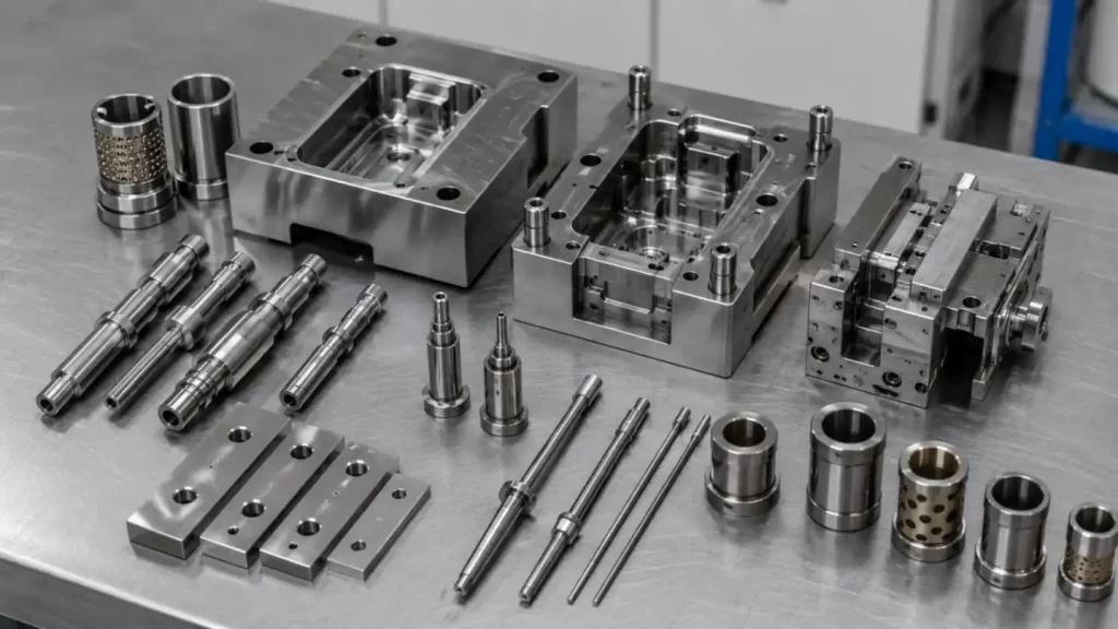
As plastic parts become smaller and more complex, custom Mould Components are increasingly required for connector molds, automotive components, medical devices, electronics, and multi-cavity tooling. In these applications, a core pin, cavity insert, or slider may need to maintain its geometry through repeated pressure, friction, thermal cycling, and mechanical impact.
The key engineering question is therefore not simply how accurately a component can be machined, but how reliably that accuracy can be maintained during production.
What Are Mould Components?
Mould Components are precision parts that form, align, guide, eject, or support the operating functions of an injection mold. They include both standard elements and application-specific components manufactured to a particular mold design.
| Mould Component | Function | Critical Control |
| Core | Forms internal geometry | Size, concentricity, finish |
| Cavity Insert | Forms external surfaces | Profile, polish, position |
| Core Pin | Creates holes/features | Runout, diameter, strength |
| Ejector Pin | Part ejection | Straightness, clearance |
| Slider | Forms undercuts | Alignment, wear, fit |
| Lifter | Releases internal undercuts | Angle, movement accuracy |
| Guide Pin/Bushing | Mold alignment | Position, coaxiality |
| Wear Plate | Supports moving interfaces | Hardness, flatness |
In precision tooling, individual Mould Components cannot be evaluated independently. Their accumulated dimensional variation forms a tolerance chain that ultimately affects the molded product.
Why Custom Mould Components Matter
Standard parts are efficient when mold geometry and operating conditions are conventional. Custom Mould Components become necessary when the tool requires unusual geometry, restricted space, micro-features, specialized materials, or controlled moving fits.
They directly affect:
• Cavity-to-core alignment;
• Molded wall thickness;
• Hole and feature position;
• Parting-line mismatch;
• Flash formation;
• Ejection stability;
• Shut-off performance;
• Cavity-to-cavity consistency.
A useful engineering relationship is:
Mould Component tolerance → assembly fit → cavity geometry → molded-part accuracy
For high-volume production, however, initial accuracy is only one requirement. Precision Mould Components must also resist wear, deformation, galling, fatigue, and thermal dimensional change.
Functional Tolerances: Tighter Is Not Always Better
A common tooling mistake is assigning very tight tolerances to every feature.
Critical Mould Components may require control of:
• Flatness and parallelism;
• Perpendicularity;
• Concentricity and runout;
• Hole position;
• Profile tolerance;
• Clearance, transition, or interference fits.
But unnecessary tolerance tightening increases grinding time, EDM finishing, inspection workload, and rejection risk.
For example, the clearance between a moving core and its mating feature must be tight enough to control flash but sufficient to accommodate thermal expansion and lubrication.
This is why functional tolerance allocation is more important than simply specifying the smallest possible number.
Selecting Materials for Mould Components
Material choice should be based on component function rather than hardness alone.
Key factors include:
• Wear resistance;
• Toughness;
• Compressive strength;
• Corrosion resistance;
• Heat-treatment stability;
• Machinability;
• Polishability;
• Expected mold life.
| Material | Engineering Characteristic | Typical Mould Components |
| P20 / 718 | Machinable, stable | Inserts, mold structures |
| H13 / SKD61 | Tough, heat resistant | Cores, inserts |
| S136 / 420 | Corrosion resistant, polishable | Cavities, medical tooling |
| SKD11 / D2 | High wear resistance | Inserts, wear components |
| Carbide | Extreme hardness and wear resistance | Micro pins, precision inserts |
A thin core pin, for example, may require greater toughness rather than maximum hardness because bending fatigue can be more critical than abrasive wear.
KT TOOL evaluates Mould Components according to geometry, molded material, production volume, wear conditions, and required tool life before selecting tool steel or carbide.
Part Geometry Changes the Engineering Strategy
Small Core Pins
Long, small-diameter pins can fail through:
• Deflection under injection pressure;
• Fatigue cracking;
• Misalignment;
• Inadequate support;
• Excessive hardness and brittleness.
Diameter-to-length ratio and loading direction should therefore be considered during design.
Deep Cavities
Deep Mould Components create additional challenges involving:
• EDM electrode access;
• Polishing accessibility;
• Venting;
• Draft;
• Heat concentration;
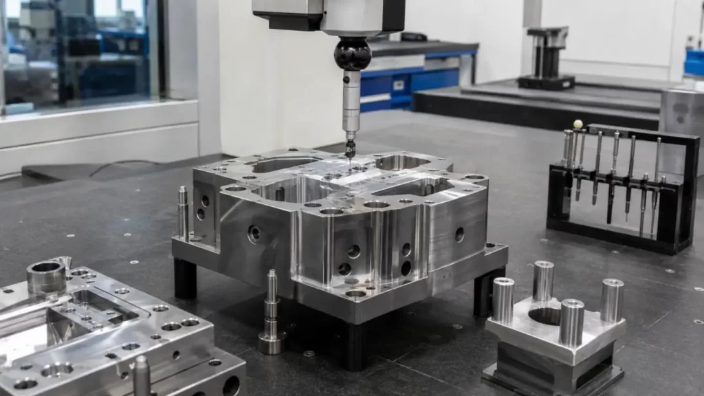
• Dimensional verification.
• Sliders and Lifters
Moving Mould Components require controlled contact conditions. Excessive clearance reduces positioning accuracy, while insufficient clearance can cause friction, galling, or seizure after thermal expansion.
Multi-Cavity Tooling
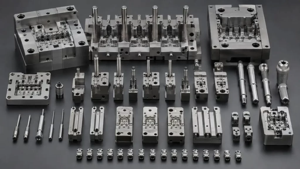
Multi-cavity molds create another requirement: component-to-component consistency.
A mold may contain individually acceptable inserts yet still produce cavity variation if their dimensions or datum relationships are inconsistent.
For multi-cavity tools, interchangeability and repeatable positioning are therefore as important as absolute dimensional accuracy.
CNC, EDM and Grinding for Precision Mould Components
High-precision Mould Components normally require multiple manufacturing processes.
| Process | Typical Application | Main Control |
| CNC Milling | Cores, inserts, cavities | Geometry, datum position |
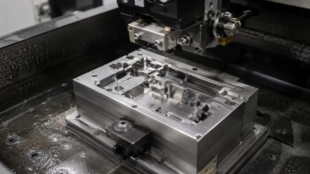
| Wire EDM | Slots, profiles, inserts | Contour accuracy |
| Sinker EDM | Deep or complex cavities | Detail geometry |
| Surface Grinding | Datum surfaces | Flatness, parallelism |
| Cylindrical Grinding | Pins and shafts | Diameter, concentricity |
| Polishing | Cosmetic cavities | Surface finish |
A typical process route may be:
CNC roughing → stress relief/heat treatment → grinding → EDM → finishing → polishing → dimensional inspection
Process sequencing matters because heat treatment can change dimensions. Critical surfaces are therefore often finished only after hardening.
Heat Treatment and Surface Engineering
Correct material selection cannot compensate for poor heat-treatment control.
Heat treatment influences:
• Final hardness;
• Toughness;
• Residual stress;
• Dimensional distortion;
• Fatigue resistance;
• Wear behavior.
Vacuum hardening and tempering are commonly followed by treatments such as nitriding, PVD, DLC, or hard chrome where additional surface performance is required.
The engineering objective is balance. Excessive hardness can increase brittleness, while insufficient hardness accelerates wear.
Surface treatment should also match the failure mechanism rather than being added automatically.
Prototype vs. Mass-Production Mould Components
The optimum design changes with the production stage.
| Stage | Main Engineering Priority |
| Prototype | Fast validation and modification |
| Bridge Tooling | Flexibility and moderate tool life |
| Mass Production | Repeatability, wear resistance, replaceability |
For mass-production Mould Components, engineers may increase wear allowance, use replaceable inserts, specify hardened materials, or apply surface treatments to high-load areas.
This prevents the prototype tooling from being overengineered and enhances the production economics for long production runs.
Balancing Precision, Tool Life and Cost
Good Mould Components are not defined by the tightest tolerance or most expensive material.
For ordinary plastic housings, carbide, ultra-tight tolerances, or advanced coatings may provide little practical benefit. For connector inserts, micro cores, high-volume automotive molds, or medical tooling, these measures can become justified.
A technically sound design balances:
Precision + Tool Life + Manufacturing Cost + Maintainability
The final specification should reflect the real operating conditions of the mold.
How KT TOOL Approaches Custom Mould Components
KT TOOL approaches custom Mould Components by evaluating the complete tooling requirement before defining the manufacturing route.
Engineering review may include:
• Component geometry and stress-sensitive features;
• Critical dimensions and datum relationships;
• Tool steel, hardened steel, stainless steel, or carbide selection;
• Sliding, sealing, and alignment surfaces;
• Heat-treatment and coating requirements;
• CNC, EDM, wire EDM, and grinding sequence;
• Prototype, bridge tooling, or mass-production requirements.
Rather than applying maximum precision to every surface, the objective is to control the features that directly influence mold function, component interchangeability, and production stability.
Engineering Mould Components for Reliable Production
Reliable injection molding results from the interaction of Mould Components, material selection, tolerance control, heat treatment, machining sequence, surface condition, and mold operating conditions.
KT TOOL offers complete support for Custom Mould Components from prototyping through to production tooling. Components will be carefully reviewed by our engineers upon the submission of your 2D Drawings and 3D CAD Files, as well as the details of your materials, tolerances, quantity, and tool life.
To receive an accurate quote for precision molds, please contact KT TOOL prior to the commencement of your molds. Our team will offer the efficient blend to meet your needs in regard to materials, machining, tolerances, and production.
FAQs
Q1. What types of Mould Components are available at KT TOOL?
KT TOOL is able to provide various custom Mould Components, including cores, cavity inserts, core pins, sliders, precision inserts, wear components, as well as other tooling components per customer drawings.
Q2. Will KT TOOL make custom Mould Components to customer drawings?
Definitely. Custom Mould Components can be made from 2D and/or 3D drawings. Customers will also need to provide information on the desired material, tolerances, surface roughness, heat treatment, and quantity for a thorough technical assessment.
Q3. What are the options for materials for Mould Components at KT TOOL?
For custom Mould Components, depending on the application, KT TOOL can consider tool steels, stainless tool steels, and carbide as well as some options of hardened steels. When considering material for Mould Components, wear resistance, toughness, corrosion resistance, and dimensional stability, as well as the desired tool life, should be taken into account.
Q4. What are the standard machining methods for Mould Components?
For precision Mould Components, if the component geometry allows, the route will most likely be a combination of CNC machining, wire and sinker EDM, a variety of grinding methods, and reflective finish.
Q5. How does KT TOOL maintain precision for Mould Components?
KT TOOL defines precision for Mould Components in functional areas such as surfaces, alignment features, sealing areas, and profiles.
Talk to the Manufacturer, Not a Middleman
Resources & Insights
-
 Industry Insights
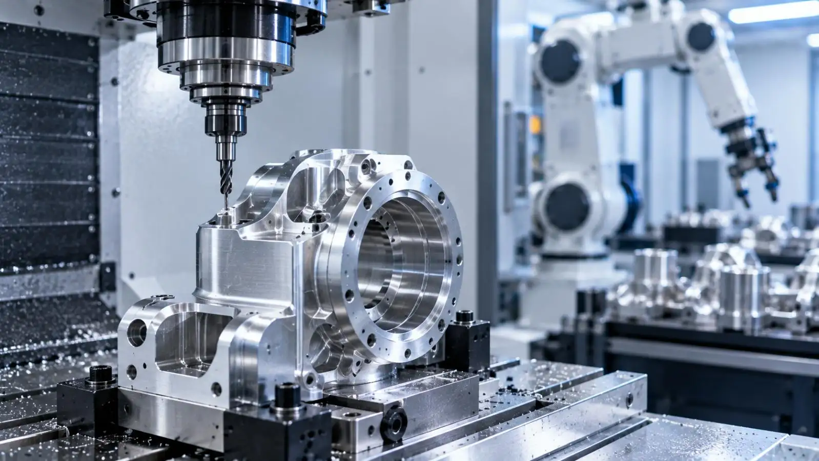
CNC Machining Robotic Parts: How GD&T Controls Robot Assembly Accuracy
2026-09-24By KT Engineering -
 Industry Insights
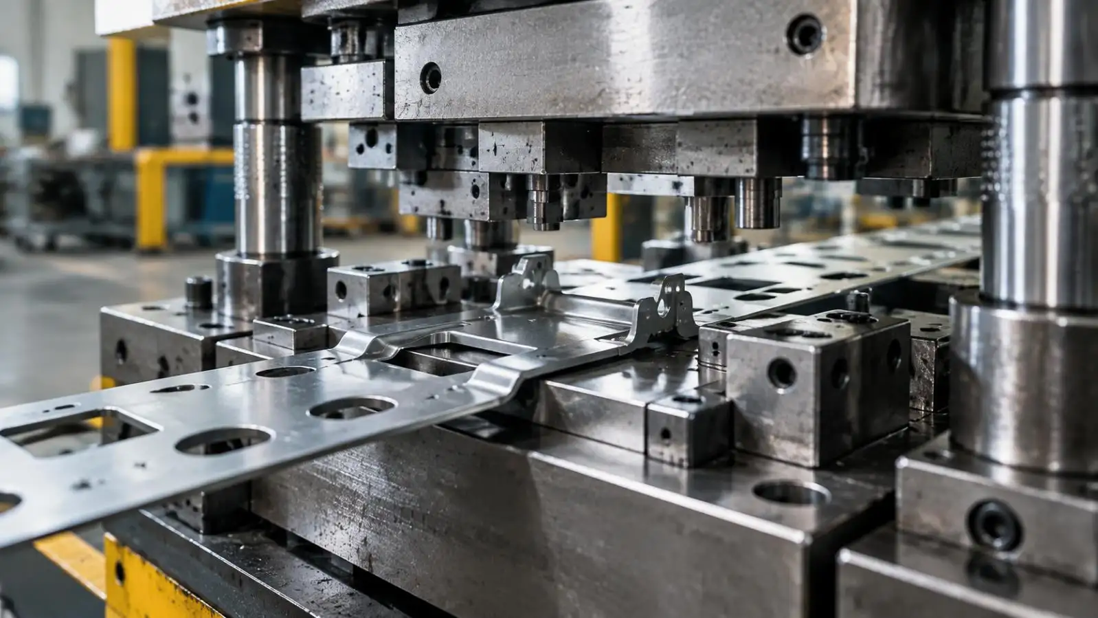
Hardware Stamping Springback Control for High-Strength Steel Parts
2026-09-24By KT Engineering -
 Industry Insights
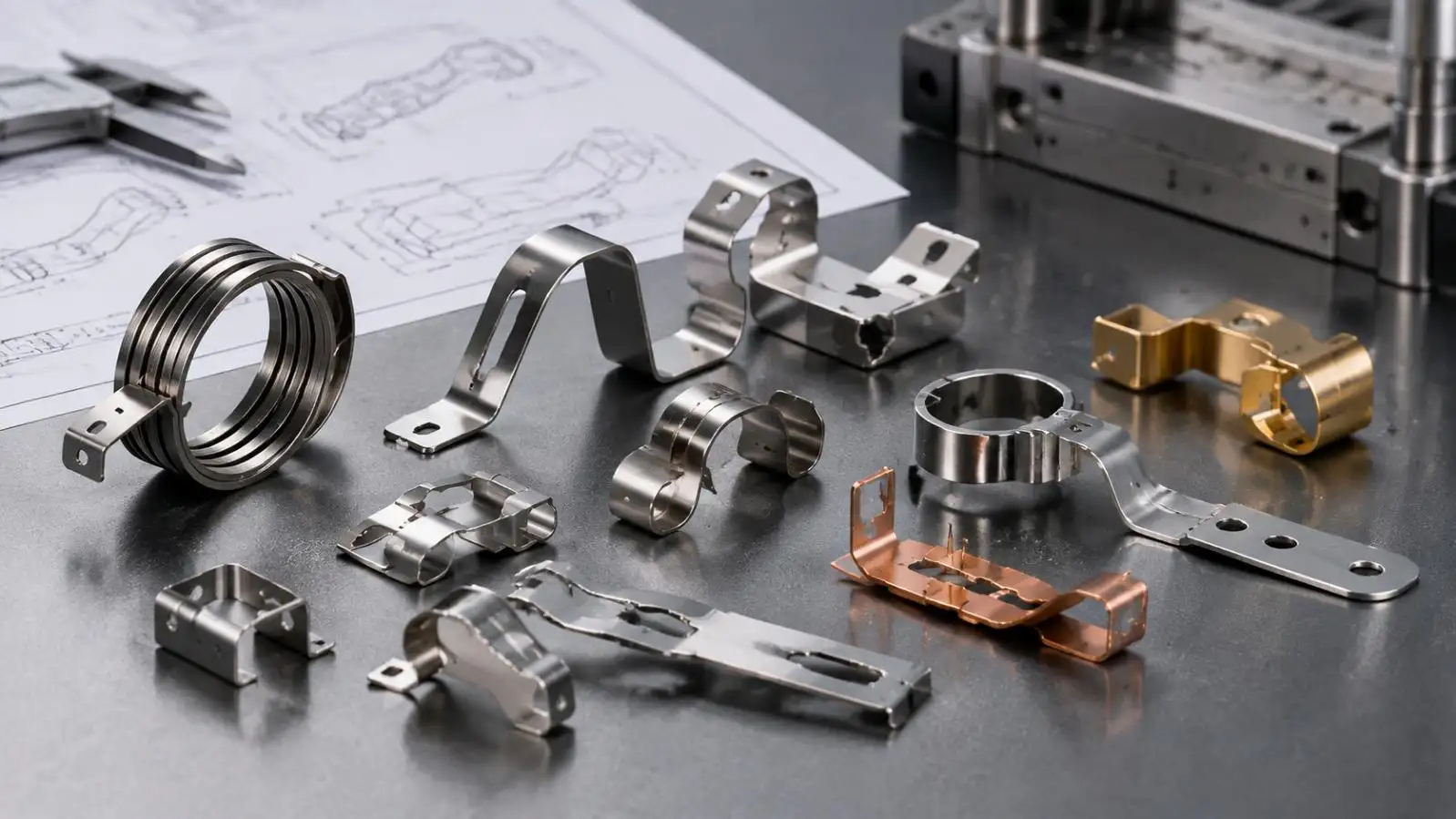
Spring Stamping Fatigue Life: How Geometry, Material and Edge Quality Affect Cycle Life
2026-09-24By KT Engineering -
 Industry Insights
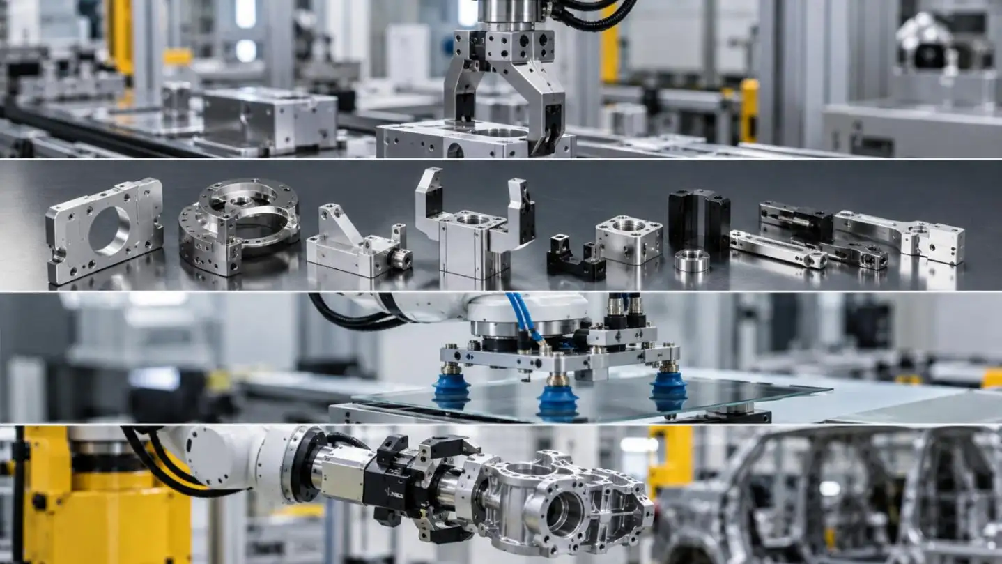
Mechanical Automation Parts for Robot End Effectors and Positioning Accuracy
2026-09-23By KT Engineering